
Projects :: FT-991(A) PTT and microphone adapter - Mark II
Intro
Back in February 2019 I made a PTT Adapter which used the stock microphone's curly lead to break-out to a phono socket for a PTT foot-switch and a 3.5 mm socket for a desk microphone. Ever since, I have had to use the multi-function knob to switch between memories, and that can involve a lot of menu navigation on the screen. So I thought it might be a good idea to replicate the Up/Fast/Down button functions from the stock microphone in a Mark II PTT Adapter. Here is how I made it:
Parts
For this build, I required:
- 3x momentary push buttons
- 3.5 mm stereo jack socket
- 2x phono sockets
- RJ45 socket
- Optional LED and holder
- A suitable Aluminium case
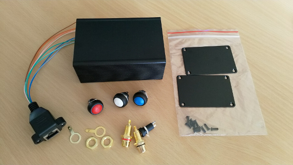
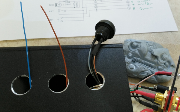
All of the parts were sourced from suppliers listed on a well-known tat-bazaar. The box measures 100 x 66 x 43 mm, and was not the usual two-part extrusion, which made fitting the push-buttons an interesting challenge. Not pictured is the LED, limiting resistor or the holder. A 100 Ohm resistor was used with a 3.3 volt colour-changing 3 mm LED. 5 volts is available via the microphone socket to power the DTMF microphone (Yaesu MH-36). The RJ45 socket was featured on my Transverter project. You have to pay careful attention to the pin-out and the colours used, as they seem to be wired up to any old "standard". I found it best to cut the RJ45 plug off, then keep it around to reference which wire had been connected to which pin.
The build
The build required drilling several holes before starting the wire-up process. Not my best hole cutting as my step drill was MIA.
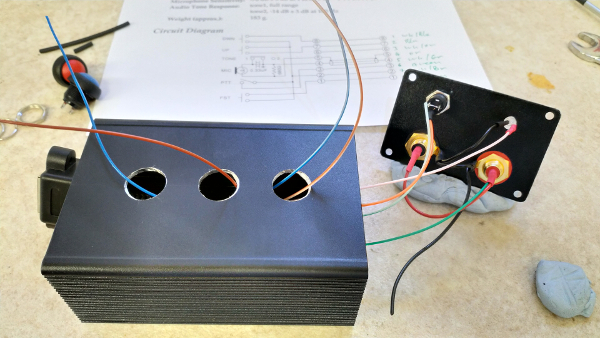
I had to fit the nut and washer before inserting the wires through the top hole. I later removed the spring washer and just used the nut - carefully tightening them with a 14mm spanner.
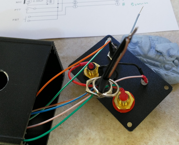
Inserting the wires and soldering them to the button. I later realised I had connected the Up and Down buttons backwards, so had to make a quick adjustment.
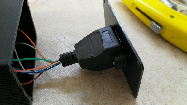
The RJ45 socket required some adjustment to fit inside:
Finished
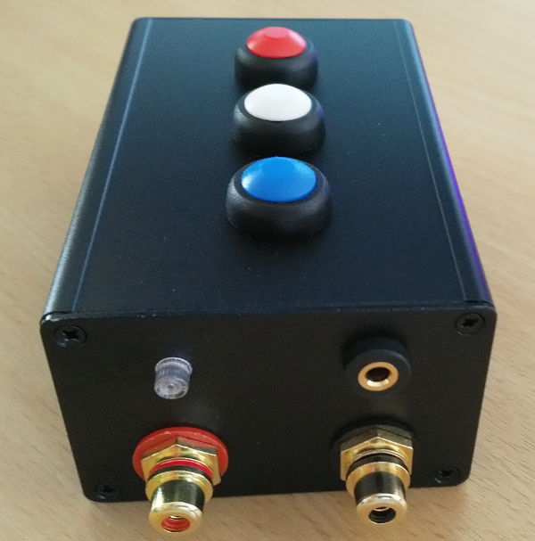
End view of the connectors. The phono connectors do not have to be insulated. They were a cheap set from the well-known tat-bazaar.
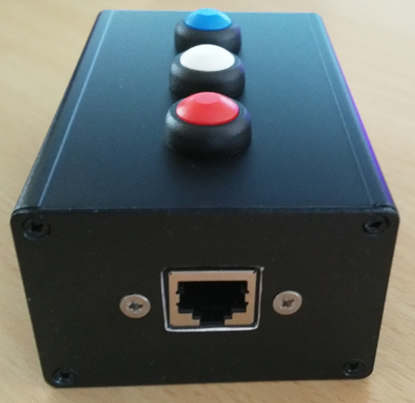
RJ45 end. Got a little carried away with the filing!
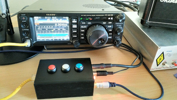
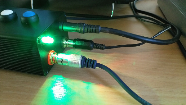
In-situ. I need to make a shorter RJ45 to RJ45 lead to neaten things up. The one featured was dragged out of the networking spares box. On the right is the microphone connector, plus the two phono connectors - one to the hand PTT, the other to the foot-switch PTT. The red button is DOWN, the white button toggles the FAST function, and the blue button is UP. I looked at LED illuminated switches, but many were expensive, large (and required a large depth inside the box), and aimed at the automotive/marine markets, so they were not really suitable. I compromised by fitting a slow-RC colour changing LED which illuminates when the radio is powered.
Here it is whilst green. A useful indication that the box is connected
I am very happy with this project. It took a couple of hours to construct. The chosen buttons require a decisive push, so there appears to be little danger of leaning on the box and accidentally moving frequency. In theory...
Page updated: 11th May 2021
Home
|
Tips
|
Awards
|
Linux
|
fldigi
|
APRS
|
QSSTV
|
WSJT-X
|
Projects
|
PSU
|
Repairs
|
Downloads
|
Links
SSTV Gallery
|
eQSL Gallery
|
MQ0PLT eQSL Gallery
|
MQ0PLT eQSL Awards