

PSU
Intro
There are a plethora of power supplies sold for Amateur Radio use that I have found, based on experience of helping other Radio Amateurs, should be avoided like the plague. This page contains some tips to help everyone gauge the best power supply to chose. The power supplies mentioned here have been tested in real-world operations. I have some unpleasant news for many of the power supply manufacturers!
The main question you will pose yourself is: "switched-more or linear?" There are pros and cons for each type of power supply. Linear power supplies can be RF quiet if positioned far enough away from your transceiver(s), although a 50/60/100/120 Hz hum can end up imposed on your transmissions. Linear power supplies are also very heavy - especially those that deliver a large amount of current. They are also thermally inefficient, often requiring huge heat-sinks and noisy fans - and fan noise can end-up being picked-up by the microphone. Many lack a fail-safe system to crowbar and blow a fuse should a regulator transistor fail. This fault condition could end-up delivering over 20 volts to your expensive equipment.
Switched mode power supplies offer a greater power density in a smaller and lighter package. They are thermally efficient and can be cheaper than their linear counterparts. The largest con with a switched-mode is the possibility to generate a great deal of radio frequency interference (QRM).
Here are some tips to look out for when choosing a switched-mode power supply:
Mains input filtering
A large number of Amateur Radio "spec" switched-mode power supplies lack sufficient input filtering on their mains port. This has two effects: (i) Conducted Emissions from other junk electronics using the same mains circuit can inject their noise into the power supply's direct-current lines; (ii) noise created inside the power supply can leak via Conducted Emissions back in to the mains circuit used in the shack.
The image below is the mains-filtering section for the Manson SPA-8230 switched-mode power supply:
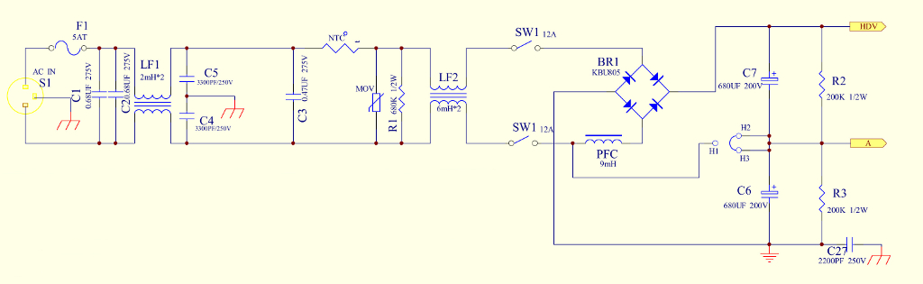
My thanks to Graham M7GRW for the pointer to a PDF of the SPA-8230 schematic. You can download it here:
 SPA-8230-Schematic.pdf
What we can see here is a double set of common-mode chokes (LF1 and LF2) complete with surge control and filter capacitors for the mains input.
Bolted to the case (on the right of the image below) is a 9 milli-Henry choke used for passive
 Power Factor Correction.
The images below are of my SPA-8230. Click on the image for a high-res (taken from a 4k photo) version.
Power Factor Correction.
The images below are of my SPA-8230. Click on the image for a high-res (taken from a 4k photo) version.
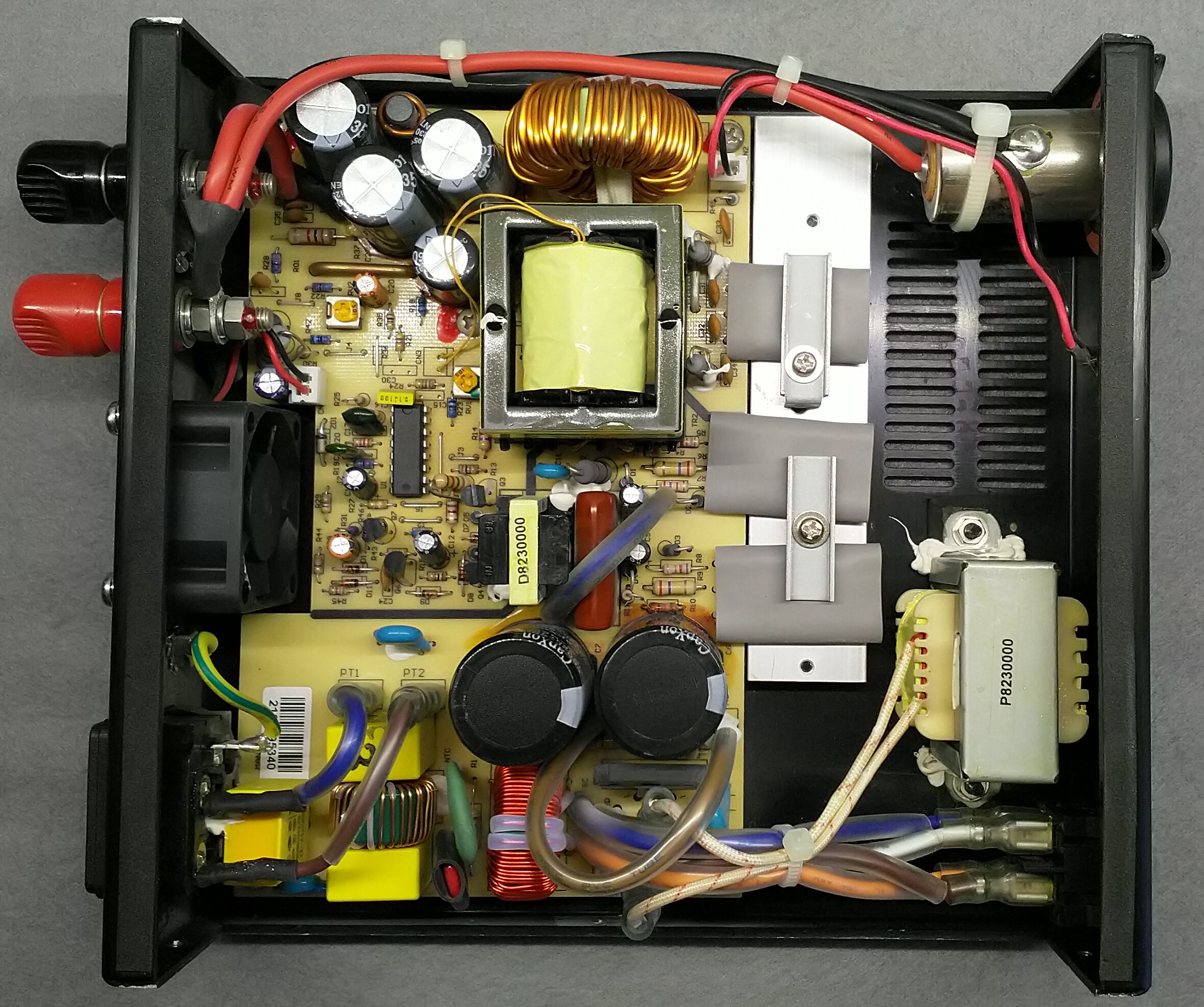
Click on the image to load a larger version (in a new window).
You may notice a lack of epoxy coating on the edge. Bare metal is also exposed on the edge of the lid to ensure a good EMC contact.
Click on the image to load a larger version (in a new window).
Click on the image to load a larger version (in a new window).
Click on the image to load a larger version (in a new window).
Click on the image to load a larger version (in a new window).
Sadly, lots of other switched-mode power supplies sold for Amateur Radio use lack this kind of input filtering.
Full disclosure: As you may have guessed, I own one of these power supplies, branded as "Sharman multiCOM". I used to have a bracket that held a 70 MHz transceiver directly above the power supply. There was no noise pick-up, unlike one sees with linear and other switched-mode power supplies. This model appears to have ceased production, although a similar model appears to be available from Nevada Warehouse (in the UK) and is sold as model PS23-SW1.
Here is an example from a power supply with various branding (this one branded as Watson Power Mite NF). The internal board is labelled AV-830IPS. Whilst this board features a standard set of filtering, it is really insufficient for radio use, and this is borne out by being a horridly noise power supply that was donated to me for testing by a local Radio Amateur.
Floating zero volt rail
A correctly designed power supply will feature a floating zero-volt direct-current rail; i.e. it is not bonded to the mains earth. Why is this important?
Mains borne noise
It is quite correct to bond the metal case to the protective earth. Should a failure occur, the case bonded to earth should allow the current disconnection safety device (ELCB/RCB) to operate. A metal case becoming live, especially with 240 Vac, can be shocking.
It is quite incorrect to bond the zero-volt rail to the protective mains earth. Why? If this path is available, all mains-borne noise (Conducted Emissions) will be conveyed to your radio transceivers and associated equipment. You will run around chasing your tail trying to eliminate the noise on the aerial system when it is actually being conducted via the mains and the d.c. wiring. This design also posses a serious risk should the neutral wire fail - see below.
Neutral failure
The majority of UK houses feature a Protective Multi Earthing (PME) system whereby the "earth" wires in your house wiring are bonded to the neutral at the 100 Amp fuse (usually in the meter cupboard). There exists a possibility that damage to a local underground supply cable will cause the neutral to fail. If this happens, any current flow in your home will look for a suitable path to earth, as the neutral of the underground supply cable is periodically bonded to a buried earth system (to protect from lightning strikes). Many Radio Amateur installations feature an "RF earth", and all radio equipment is usually bonded to this quiet earthing system. If the zero-volt rail in your mains power supply is bonded to earth, it provides a path, via your radio equipment, to your quiet RF earth. Considerable current could flow along this path potentially causing wires, which are perhaps only rated for 25 Amps, to overheat and catch fire. Radio equipment and their associated interconnects could also suffer damage, and the wet conductive meat-bag operating it may find themselves receiving a nasty shock. A neutral disconnect in the UK could see the incoming phase (live) rise to 415 Vac. It is therefore very important to ensure the zero-volt rail of your power supply is not connected to the mains earth!
The AV-830 board (detailed below) is a poor design as the zero-volt rail is bonded to the mains earth. This fails on both safety and interference.
Poor design
You might think I am picking on the AV-830. I have seen other makes of this type of power supply using this same technique, and it is a seriously flawed design.
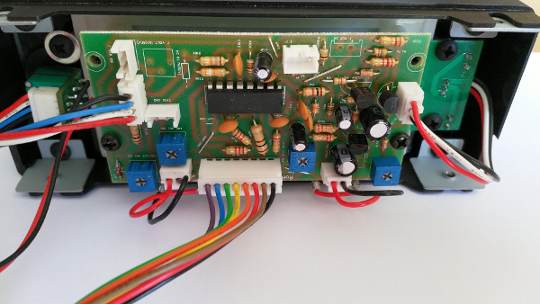
The image above is the front panel [of the Watson Power Mite NF]. In order to produce a compact design, and provide current and voltage meters, the designers have placed the switched-mode controller chip on this circuit board. The multi-coloured ribbon cable carries the control pulses to the main-board and on to the FETs that control the switching of the transformer. There is still no suitable test for Radiated Emissions below 30 MHz, and so the designers have failed to understand that even short leads like this can radiate interference. I also find the use of cheap 10% resistors quite poor! We also find this design (and others like it) feature a control on the front panel to alter the switching frequency used to drive the FETs. This adjustment clearly demonstrates that this design suffers from considerable Radiated Emissions, and all power supplies that feature this adjustment should be avoided!
Nevada PS23SW1
I recently purchased one of these power supplies to act as a spare should my main power supply fail, or for those times where I can set up /P for Blue Ham. Now my Meinberg Time-Server runs from my 13.8V supply (plus 95 Ah battery) it is not practical to strip the power system down to take it elsewhere. The power supply retails (at the time of writing) for £59.95 plus delivery. The Manson SPA-8230, which is clearly the Gold-standard (unless or until I can test others), used to retail for around £85. The price difference shows in the construction of the Nevada power supply. I give it 4 out of 5 stars for matching interference suppression and design size. It sadly fails on the most important test: the zero-volt rail is bonded to mains earth!
What to do? Return it for a refund, knowing that many of the power supplies sold are simply rubbish, or invalidate the warranty and fix it? I chose the latter.
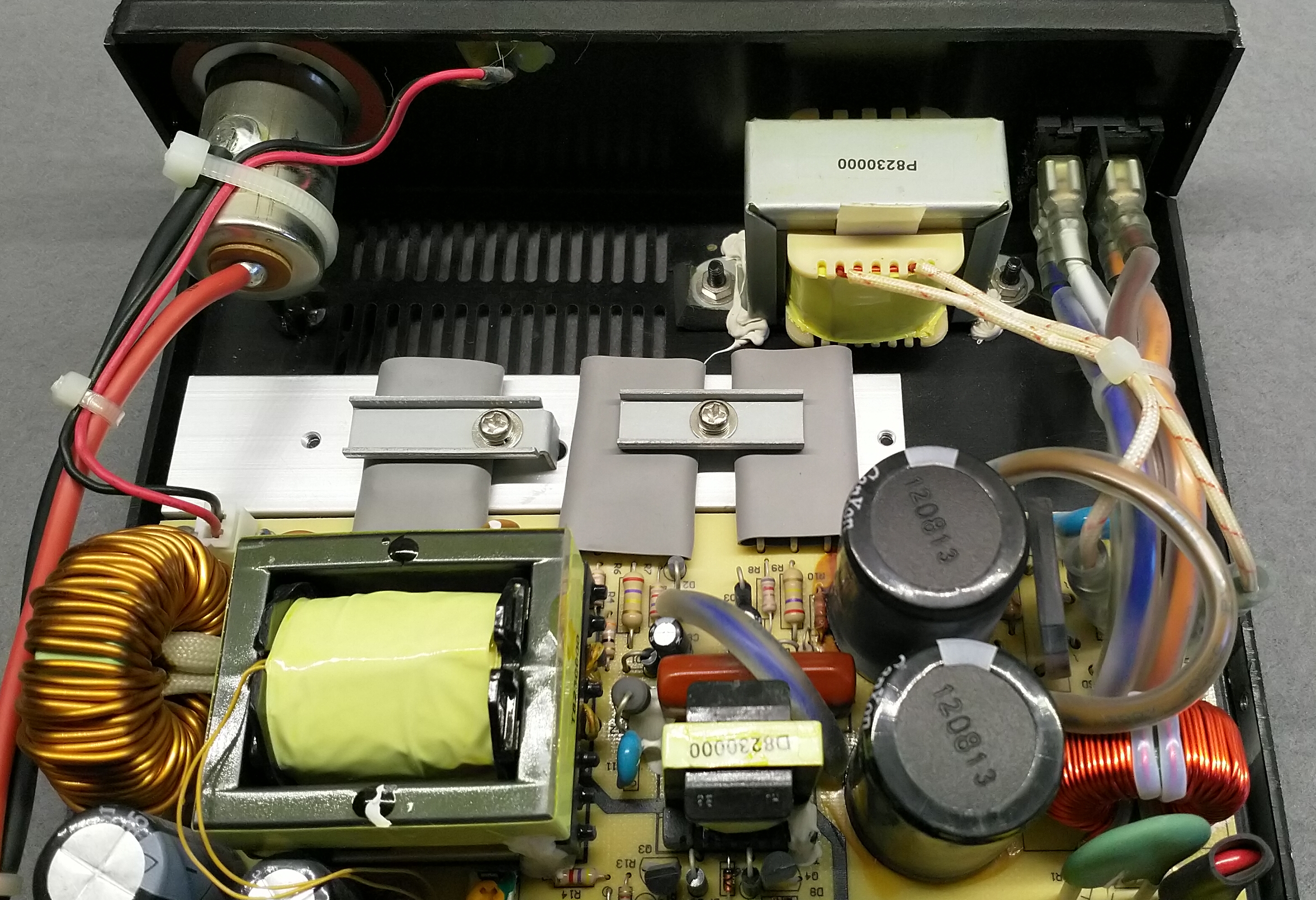
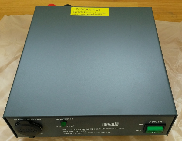
Top view: The warning label for heat is probably a bit overkill. I have run 100 Watts on FT8 via my FT-991A and the Manson SPA-8230 has barely run its internal fan. Having spent a weekend running 100 Watts for Blue Ham October 2021, I can state that this PSU never even warmed up.
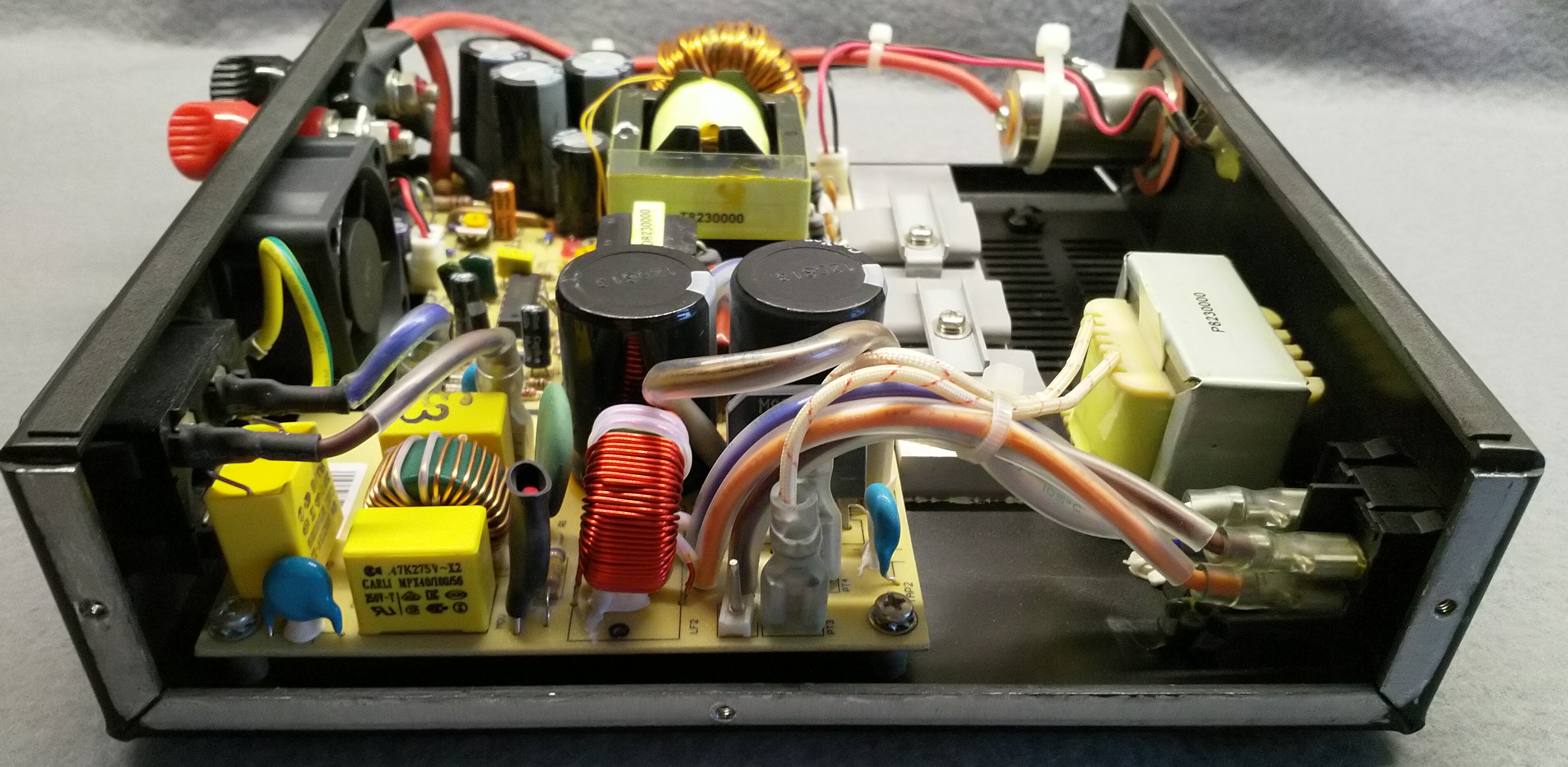
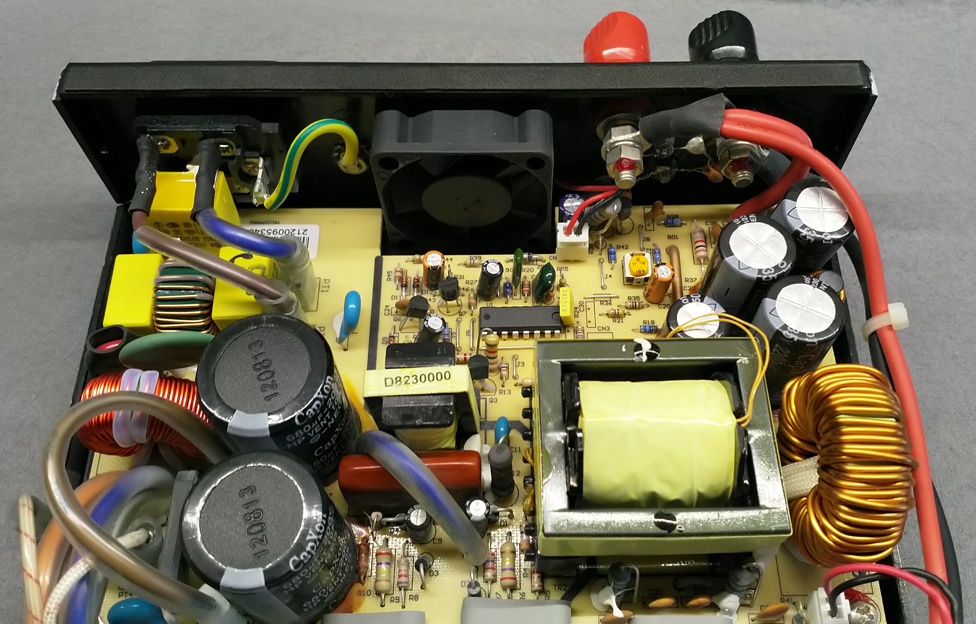
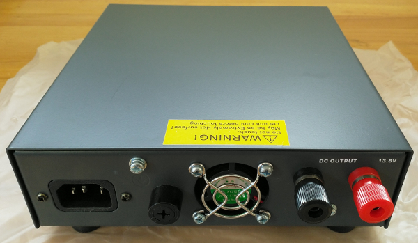
Rear view:
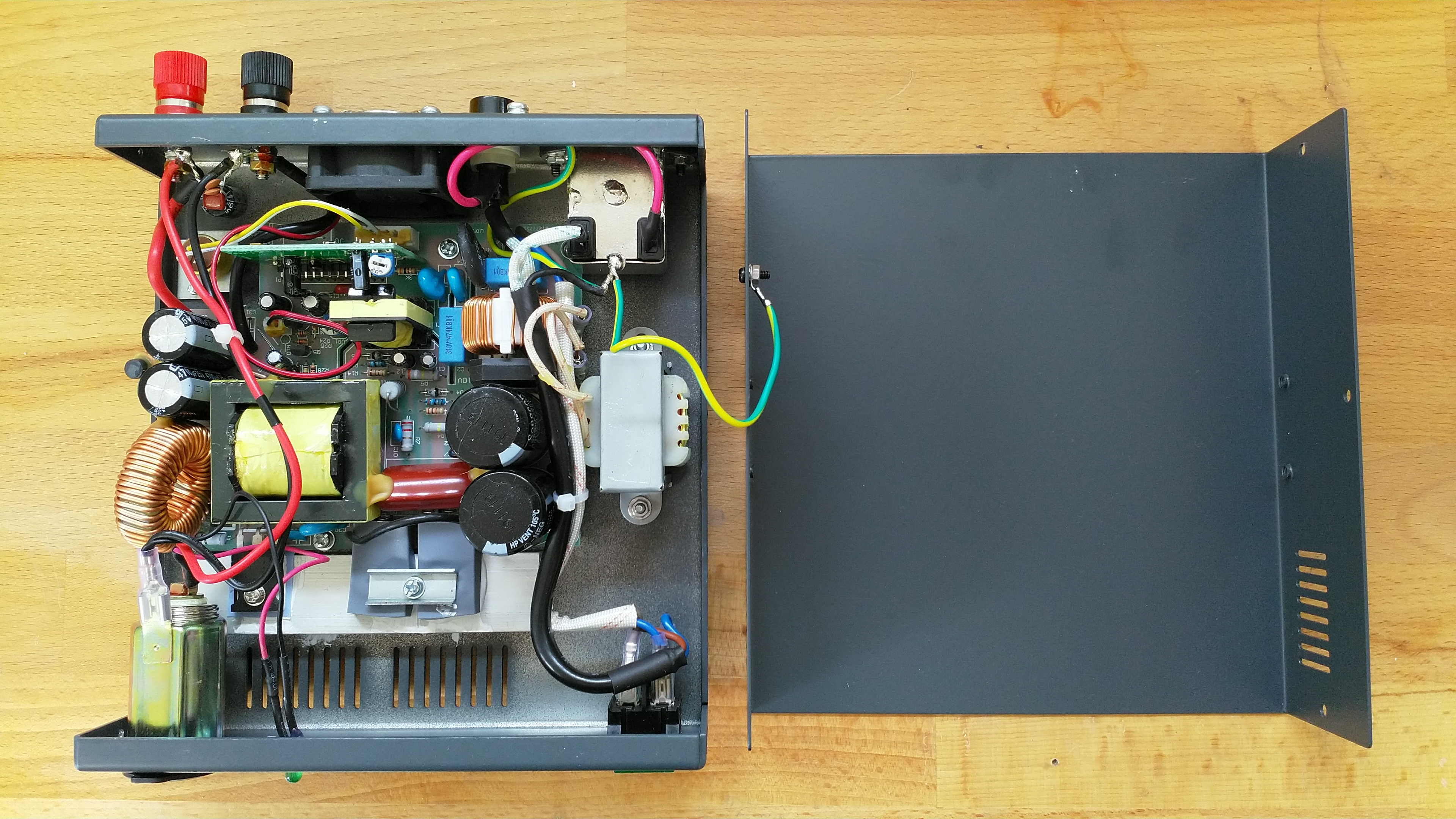
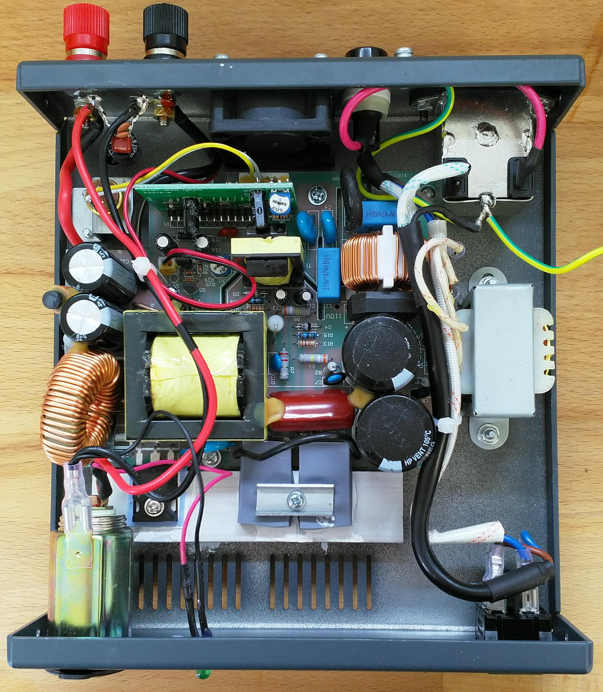
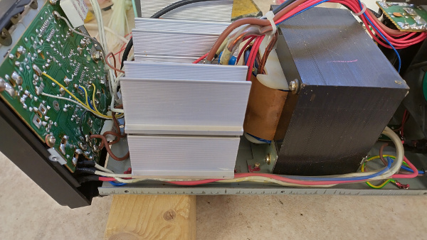
What is inside? The manufacturers have chosen to epoxy coat all of the surfaces (the SPA-8230 mating edges are bare metal) requiring a slightly annoying earth lead to bond the lid. This is easy to remove for modification purposes. Remember to put it back after!
Click on the image to load a larger version (in a new window).
You want to get closer? The design of this power supply ticks a number of boxes. A shielded mains-input filter; extra
filtering on the main board;
Power Factor Correction;
and spike suppression all make for a quiet power supply. Unfortunately, you will have already noticed the cheap and naff cigar
lighter socket present lower left. This non-insulated nasty bonds the zero-volt rail to the mains earth, which is a huge fail!
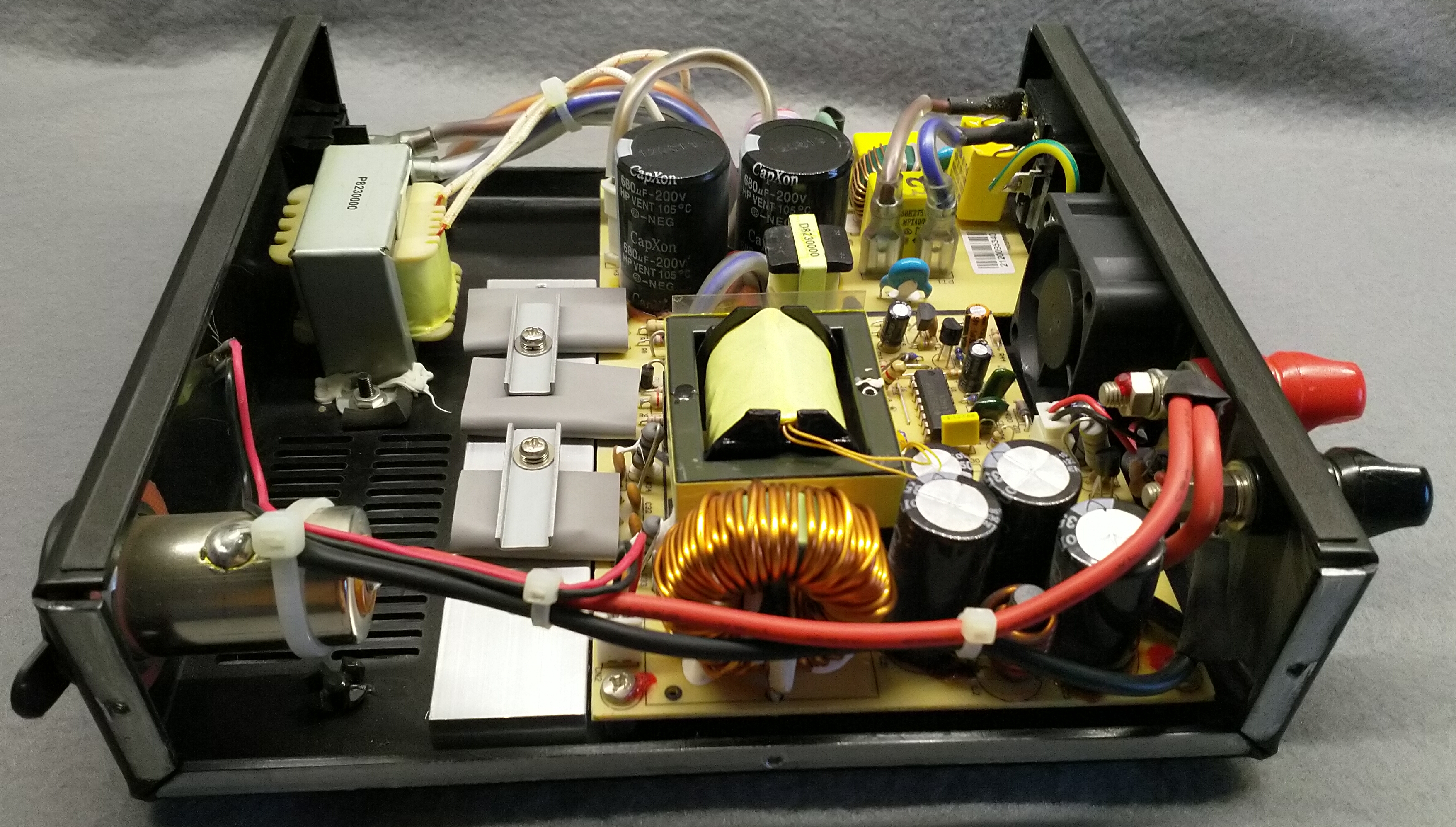
Click on the image to load a larger version (in a new window).
The horror!
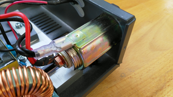
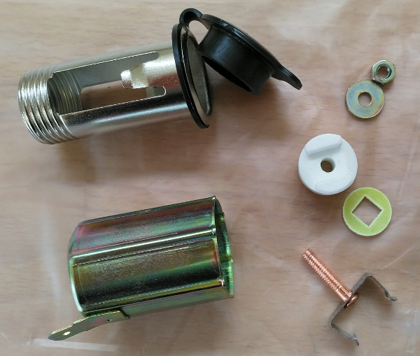
Exploded view after removal. Yes, it is an actual cigar lighter socket one would find in a car. Insert the heating element to light your cigar. Sent off for recycling!
You might think you can solve the grounding problem by removing the negative lead connecting the socket. And you would be wrong. Safe in the knowledge that a cheap non-insulated "power socket" was being used, C31 is has been linked - thus providing another path to mains earth.
We can rebuild it!
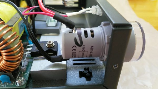
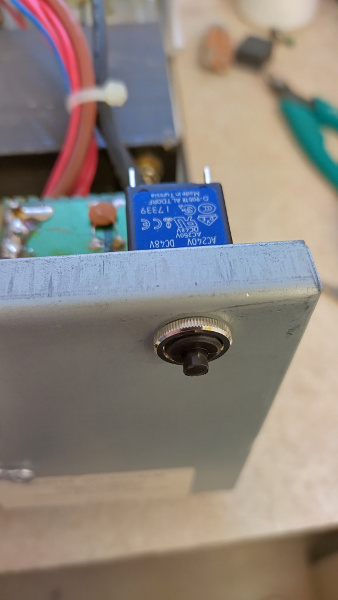
Removing the cigar lighter socket and the snotty bit of glue trying to hold the very boring green LED in place. Unfortunately the hole is too small to take many of the insulated power sockets available for marine use, and as I lack a step-drill large enough, I found something else to fill the hole. If memory serves, it is 23.7mm diameter; but please do not take my word for it! You may wish to enlarge the hole and fit an insulated power socket - available from a well-known tat-bazaar.
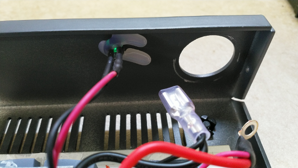
Board out! You will need a 7mm spanner to disconnect the binding post wires. Remove all of the screws on the board, plus the two holding the FETs and diode in place. The board should pop out as shown. You will need a powerful soldering iron and de-soldering braid to cleanly remove the link in C31.
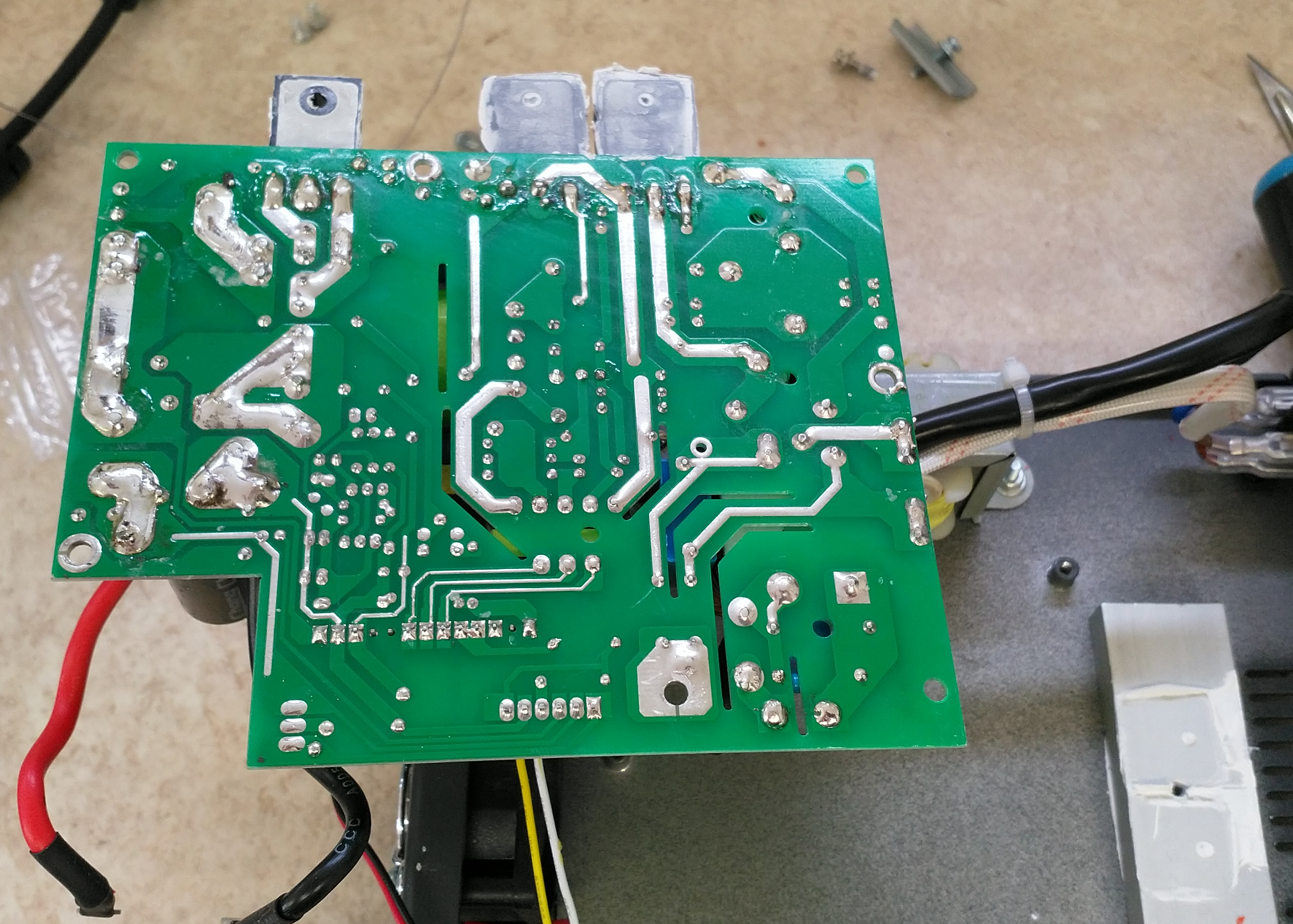
Click on the image to load a larger version (in a new window).
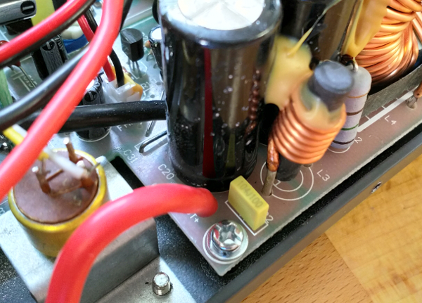
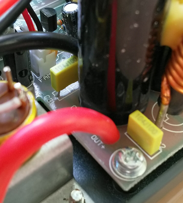
C31 fitted: There is no schematic or bill-of-materials for this power supply, so I took an educated guess and ordered the same capacitor as fitted to C32. It is marked 104J100 and is a Polypropylene safety capacitors CL71 rated at 100 Volts, with a value of 100 nF. The PCB spacing was clearly designed for a larger capacitor (7/8 mm pin spacing) so my 5 mm spaced capacitor had to stick out of the board a little. It is important to use the correct safety capacitor and not any old 100 nF you may have lying around!
Pro tip: When re-fitting the board, fit all of the screws loosely, then tighten the screw nearest the FETs, screw down the FETs and diode, then tighten down the rest. This should ensure you do not place any twisting stress on the leads.
I changed the boring LED for a water clear version and fitted a different LED clip. When you remove the binding post nuts to remove the main-board output leads, the socket and LED wiring harness can be removed for modification - if you so wish. I found something with a 22mm diameter to fit the hole...
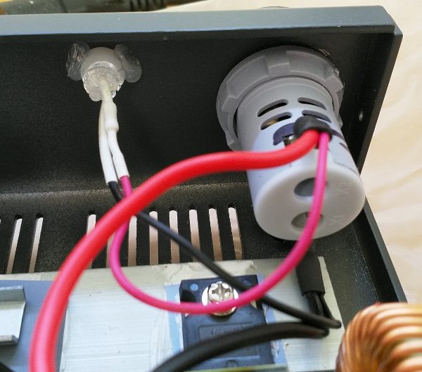
I changed the original connectors for the "power socket" to small screw terminal crimps. I removed the plastic sleeve and soldered the wires in direct before adding a little adhesive-lined heat-shrink as the Red crimp did not have enough space to handle the two sets of wires (and I do not have any Blue crimps in that style). Can you guess what it is yet?
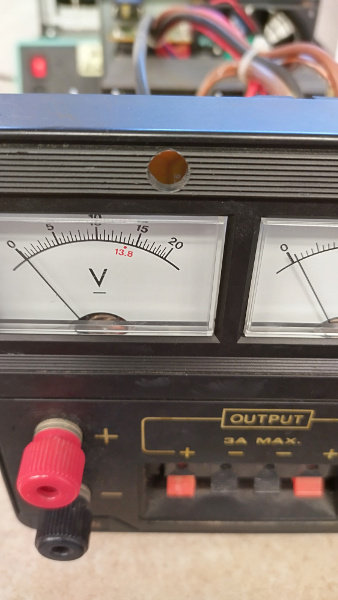
Wonder no more. It is a 22 mm LED volt meter sourced from a well-known tat-bazaar (try searching for "22mm 6-100V DC Digital Display Voltmeter Indicator LED Lamp Round Signal Light"). And the boring green is now a rather bright blue - even with the original 1 k limiting resistor. Good job I did not fit one of my spare 20 candela blue LEDs!!
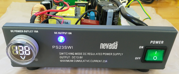
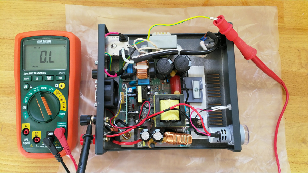
Acid Test! Just to prove the above modifications work, here is my DVM showing an open circuit between the zero-volt rail and the mains earth. This power supply is now safe to use!
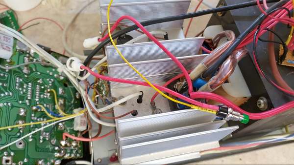
Manson EP-925
A local Radio Amateur came to me with one of his two Manson EP-925 linear power-supplies seeking repair. It had suffered
the standard linear power-supply fault: one of the 2N3055 transistors had failed dead-short. So instead of a nice regulated
13.8 volts, the full non-regulated 25 volts was present on the front panel. Most amateur radio equipment will tolerate up
to 15 volts as they are design to work in vehicles with a 12 volt system, where the battery charging system in the alternator
can supply up to 14.4 volts to ensure a proper charge. Anything higher than 15 volts could start to cause serious damage.
After fixing the power supply - twice, as there are a lot of fake 2N3055 transistors out there - the Radio Amateur asked
if I could add-in an over-volt protection circuit as he had seen on
PA0FRI's page.
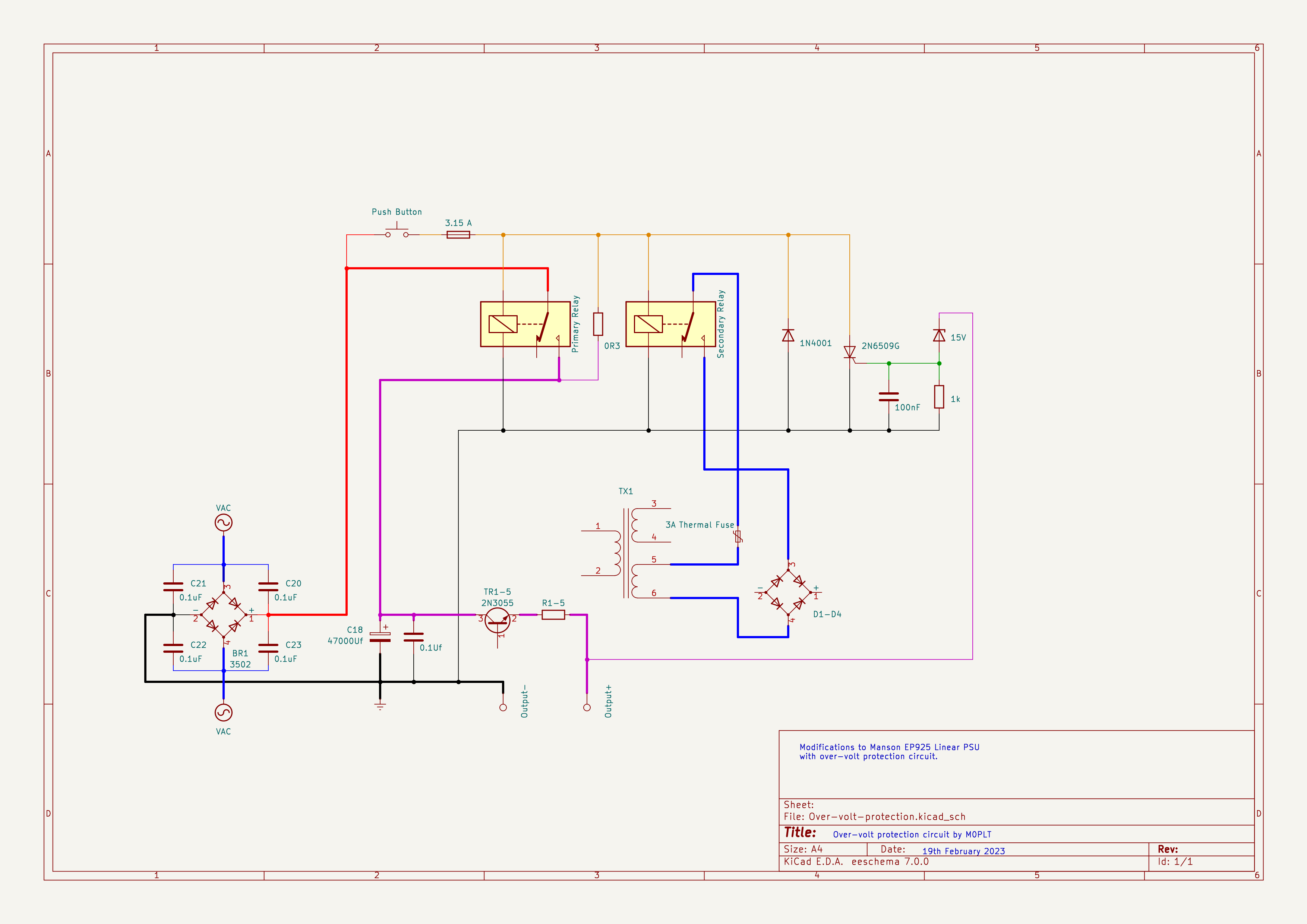
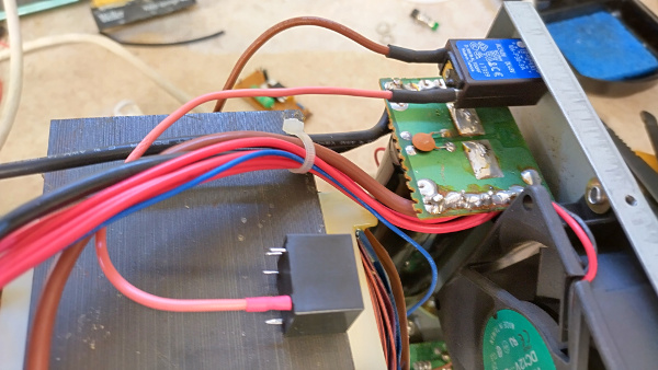
I decided the clever choice was to use relays to disconnect the power instead of trying to crow-bar over 20 amperes of current to blow a fuse. The circuit below includes parts of the Manson EP-925 circuity to highlight the areas where the modifications are fitted.
Click on the image to load a larger version (in a new window).
How does it work? When the mains switch is set to ON the transformer and the high-current bridge-rectifier energise. At this point, the relays are open and no current can flow to the control circuitry. Pressing the "Start" button added to the front panel applies the un-regulated 25 volts to the two 24 volt relays to energise them. Current now flows from the primary relay Normally-Open output via a 0.3 Ohm resistor to power both relays. Any time the power-supply is started up, the "Start" button must be pressed to energise the relays.
Protection If the main output voltage exceeds 15 volts, the Zener diode starts to conduct. If the voltage developed across the 1k resistor exceeds approx. 700 mV (15.7 at the output-terminals), the thyristor (a 2N6509G in this case) is triggered. This creates a short-circuit across the relays which is current-limited via the 0R3 resistor. This has the effect of releasing the relays and thus removing the voltage from the regulation circuitry. The trigger works if the user increases the output past 15.7 volts or if a 2N3055 were to fail dead-short.
What is the 3A breaker for? The 3A breaker is fitted to provide protection to the low-current regulation side of the circuitry. Should the high-current bridge-rectifier fail, a fault-path exists via the Base-Emitter of the TIP31C transistor and any of the 2N3055 transistors. This path could try to provide more current than the low-current side of the power-supply can provide.
Why the fuse? If the user tries to press the "Start" button whilst the power-supply is in a fault-condition; i.e. the output control is too high, or a 2N3055 has failed, the thyristor will try to sink all of the current of the high-current bridge-rectifier. This can be around 30 amps and more than capable of destroying circuitry. The 3.15 amp fuse is present to blow and prevent damage to the rest of the circuitry. Yes, it would be nice to design this to work on the low-current side, but in this power-supply, all of that circuitry is buried on the front panel, and that requires a greater amount of modification.
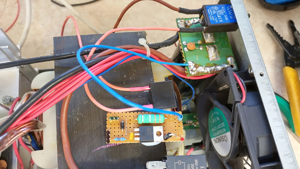
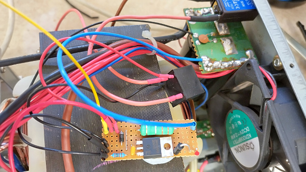
Vero board
The above circuit, consisting of the zener diode, the 1k resistor, a 1N4001 back-EMF protection diode, a 100 nF capacitor, the thyristor, and the 0R3 resistor can be assembled on a small piece of Vero board.
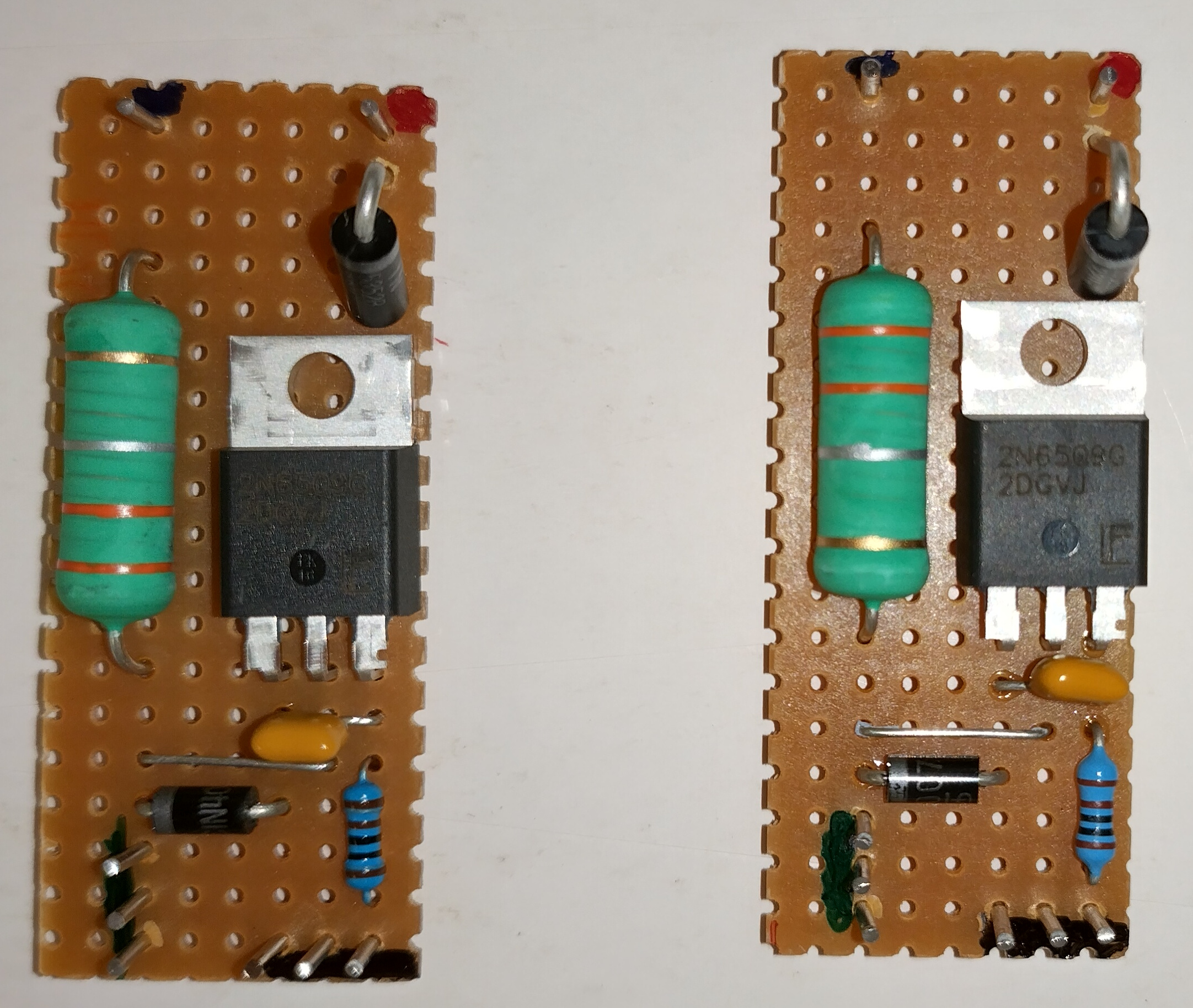
Click on the image to load a larger version (in a new window).
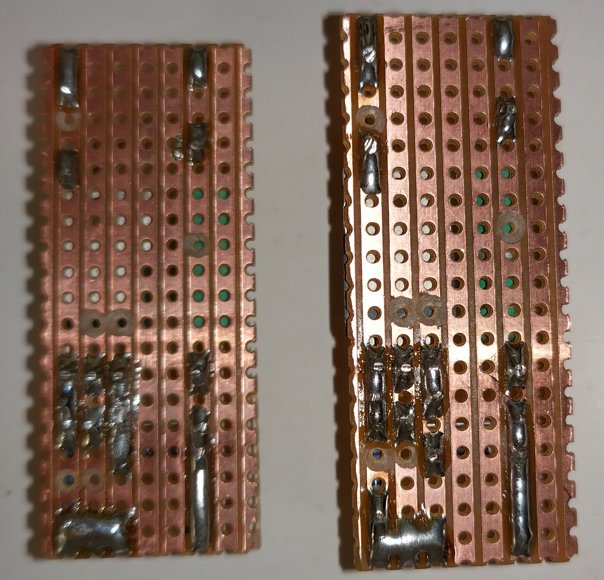
Click on the image to load a larger version (in a new window).
Installation
1. After removing the cover, it is a good idea to place a 1k resistor across the terminals of the 47,000 uF capacitor to discharge it fully before you start working on the power supply. In this version of the EP-925, we also need to cut-off the protruding capacitor legs to stop them fouling on the breaker we are going to install.
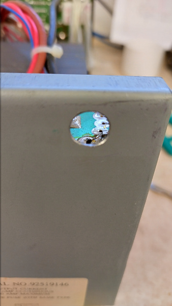
2. Drill a hole in the rear panel to fit the 3A thermal breaker. The thermal breaker used here requires a 9.5mm hole.
3. Drill a 7mm hole (or to suit your choice of push-button) in a suitable part of the front panel for the "Start" button.
4. Remove the screws holding the front panel to the main chassis. You may find it helpful to prop the front part of the chassis on a block of wood.
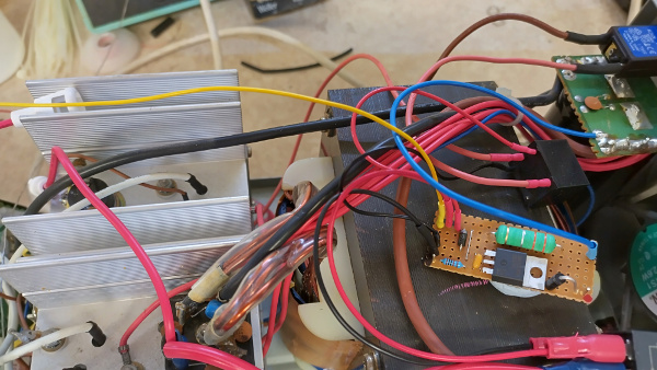
5. De-solder the indicated wire from the transformer secondary and route it to the newly installed 3 Amp breaker. Connect a wire around 18AWG from the breaker to the low-current relay.
6. Connect another 18AWG wire from the COM of the relay to the bridge-rectifier input on the front panel.
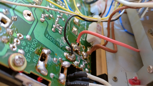
6. Remove the +VE output from the bridge rectifier and re-terminate with an insulated crimp. Take a short length of 32/0.2 wire and fit spade-socket crimps either end. Fit one half of the fuse-holder to the bridge rectifier output end.
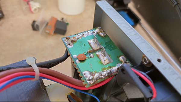
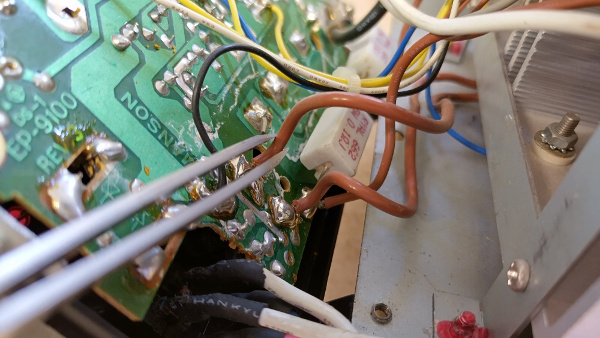
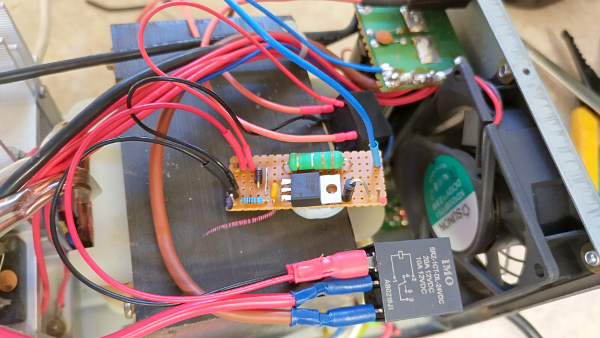
8. Solder a wire (blue in the image below) from the reservoir capacitor +VE to the 0.3R resistor. This is easier than trying to fit a small wire alongside a larger one when crimping.
9. Connect the relay coils to the circuit board.
11. Connect the second side of the "Start" push button to the circuit board.
12. Solder the other end of the fuse-holder to one side of the push-button.
13. Connect the zero volt rail of the circuit board (black wire in the image below) to the reservoir capacitor -VE (using the solder pad near the ceramic capacitor).
14. Connect a sense wire from the Zener input to the front panel +VE output (not photographed).
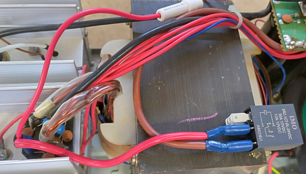
A spot of hot-melt glue can be used to affix the relays to the transformer; and the circuit board can be encased in heat-shrink to avoid short-circuits.

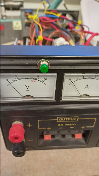
The "Start" button fitted.
Page updated: 19th March 2023
Home
|
Tips
|
Awards
|
Linux
|
fldigi
|
APRS
|
QSSTV
|
WSJT-X
|
Projects
|
PSU
|
Repairs
|
Downloads
|
Links
SSTV Gallery
|
eQSL Gallery
|
MQ0PLT eQSL Gallery
|
MQ0PLT eQSL Awards