
Repairs
On this page I detail radio equipment I have repaired as a reminder to myself, and as a help to others who may come across odd faults.
May 2021 - Yaesu FT-8900R
A local 2E0 (now sadly SK - 12th August 2021) asked me to look at his FT-8900R. "It has gone quiet..." was the description of the fault. Upon investigation, the internal speaker certainly seemed to go "quiet" when you turned the volume up on either of the volume controls. There was no problem with the external speaker, and I quickly learned, after referencing the service manual, that the external speaker has its own power-amplifier.
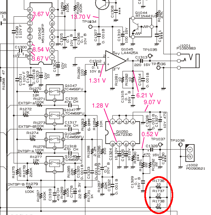
So what was the fault? I traced the fault to three 10 Ohm surface mount resistors which are configured in parallel to provide a 3.33 Ohm current-limit to the internal speaker PA chip. It would appear that if you use this radio with its internal speaker set to a high volume, you will over-heat these resistors and burn them out. In the sample of the schematic below, we can see R1736, R1737, and R1738 provide a current-limit to the 9 Volt line that feeds the TDA7233D chip. The internal speaker connects to J1002.
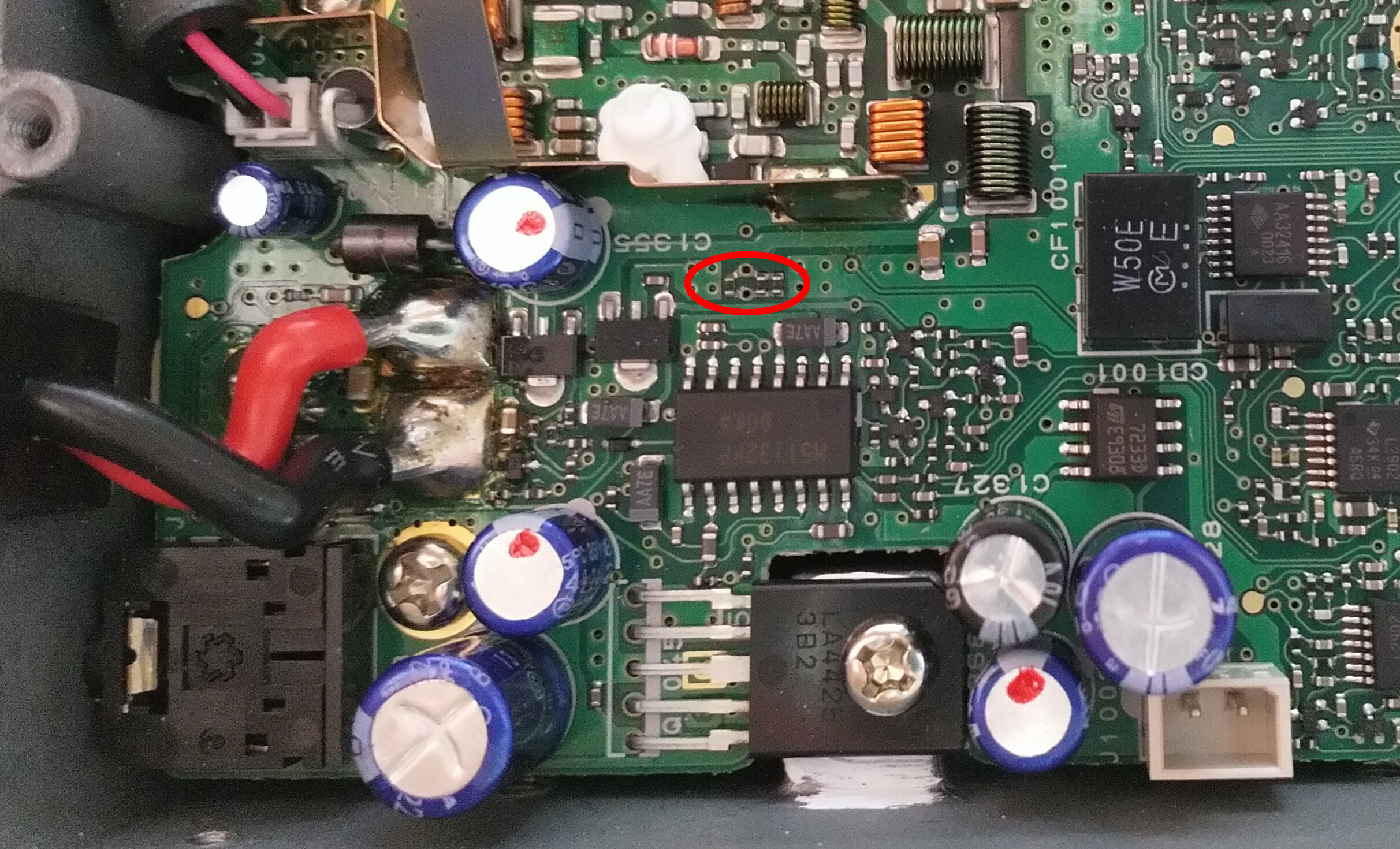
Where are those resistors on the board? Thankfully, they are on top of the board, and they can be changed with suitable surface-mount soldering equipment. The Yaesu part number is: J24189001 and I recommend ordering 5 off, as you are bound to blow one away with the surface-mount hot-air re-work tool. Here is a picture I managed to take with my Nokia 8 and my 3.5x magnifying glasses prior to changing them:
Click on the image to load a larger version (in a new window).
I would have preferred a standard 0.25 Watt through-hole resistor here, but there is very little space, and you have to be careful to not create a short-circuit with the 9 Volt rail. Having changed those three resistors, and another broken front-panel part, the radio is back to full working order.
July 2019 - Yaesu FT-767GX
A local G4 Radio Amateur approached me with a query on programming his Yaesu FTM-100. Whilst at his shack, he mentioned and demonstrated his FT-767GX (and FL-7000) and its amnesia. I said I could change the batteries as I had carried out similar repairs on an old FT-757. So here is my guide on how to go about it:
Local Unit battery
After removing any optional modules and opening up the radio, you will find the Local Unit circuit board buried under the baffle plate that supports the optional modules. This will need to be removed in order to remove the Local Unit board. I recommend taking high-resolution photos so you have a record of where all of the connectors go.
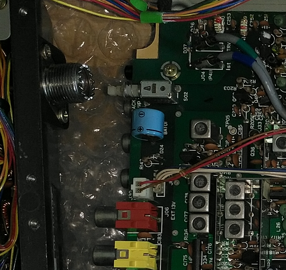
This image shows the radio opened up, the baffle removed, and the battery on the Local Unit board:
Click on the image to load a larger version (in a new window).
After removing the board, the old dead battery was removed. A CR2032 coin-cell holder makes for a suitable replacement modification. In future the battery can be changed in a few second without resorting to complete disassembly. In the next picture, I have a CR2032 coin-cell holder, tinned copper wire, and some foamed plastic construction board (I had in the spares box) that will provide a spacer. Similar materials could be used to provide a 4 or 5 mm space.
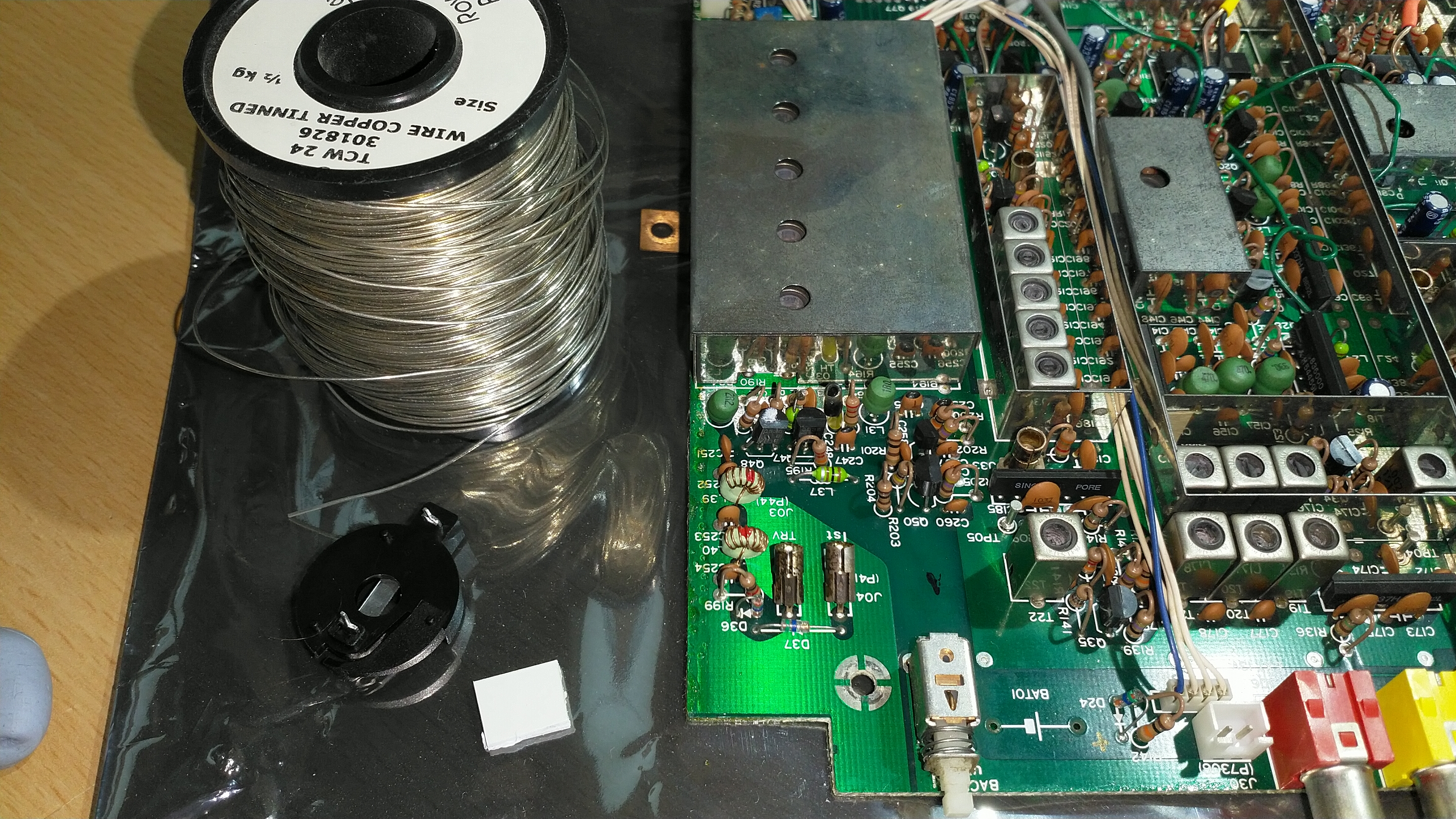
Click on the image to load a larger version (in a new window).
Two pieces of the high-impact polystyrene board (available on ebay) are glued with cyanoacrylate and small leads are soldered onto the cut-down pins of the cell holder.
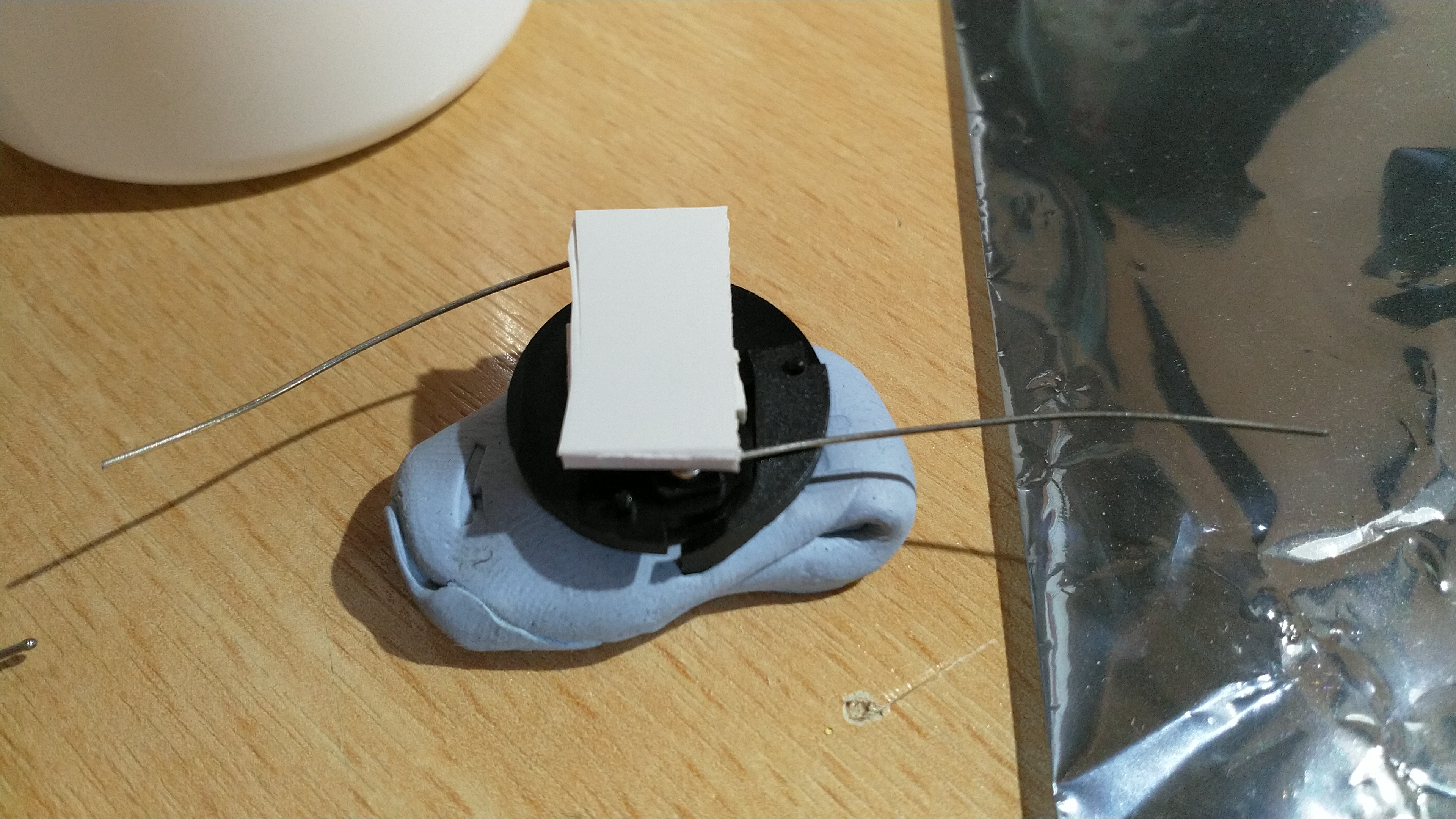
Click on the image to load a larger version (in a new window).
I neglected to photograph the extra modification required to fit the holder to the board. One of the leads needs to tuck under the plastic spacing, so I melted a slot with the soldering iron to provide a small tunnel. This ensured a flat gluing surface when finally fitting the holder to the circuit board.
The following picture details the battery holder glued to the board:
Click on the image to load a larger version (in a new window).
It may be possible to replace the battery with a 3 Volt rechargeable solution, however, this will require modifications to the circuit board in order to provide a regulated 3 Volts. Over-charging batteries tends to make a mess!
Aerial Matching Unit
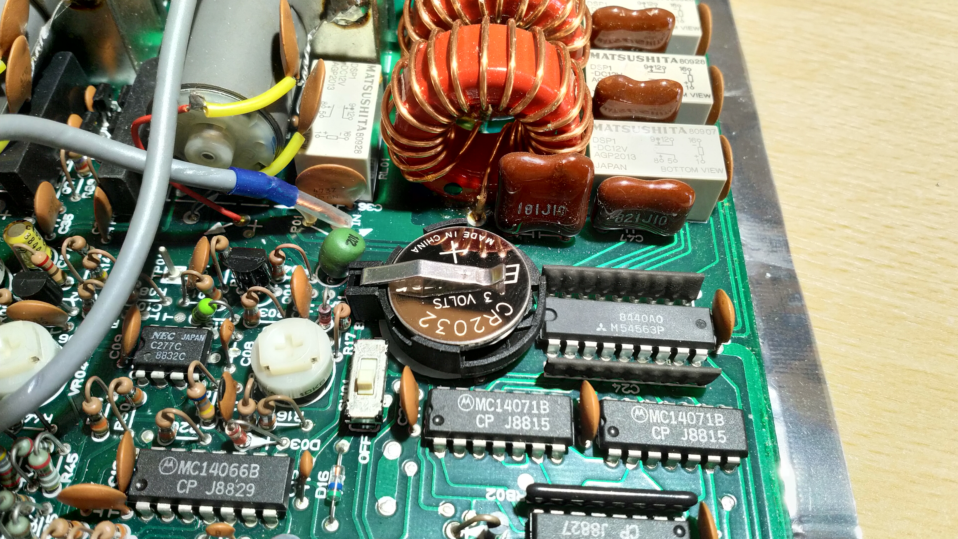
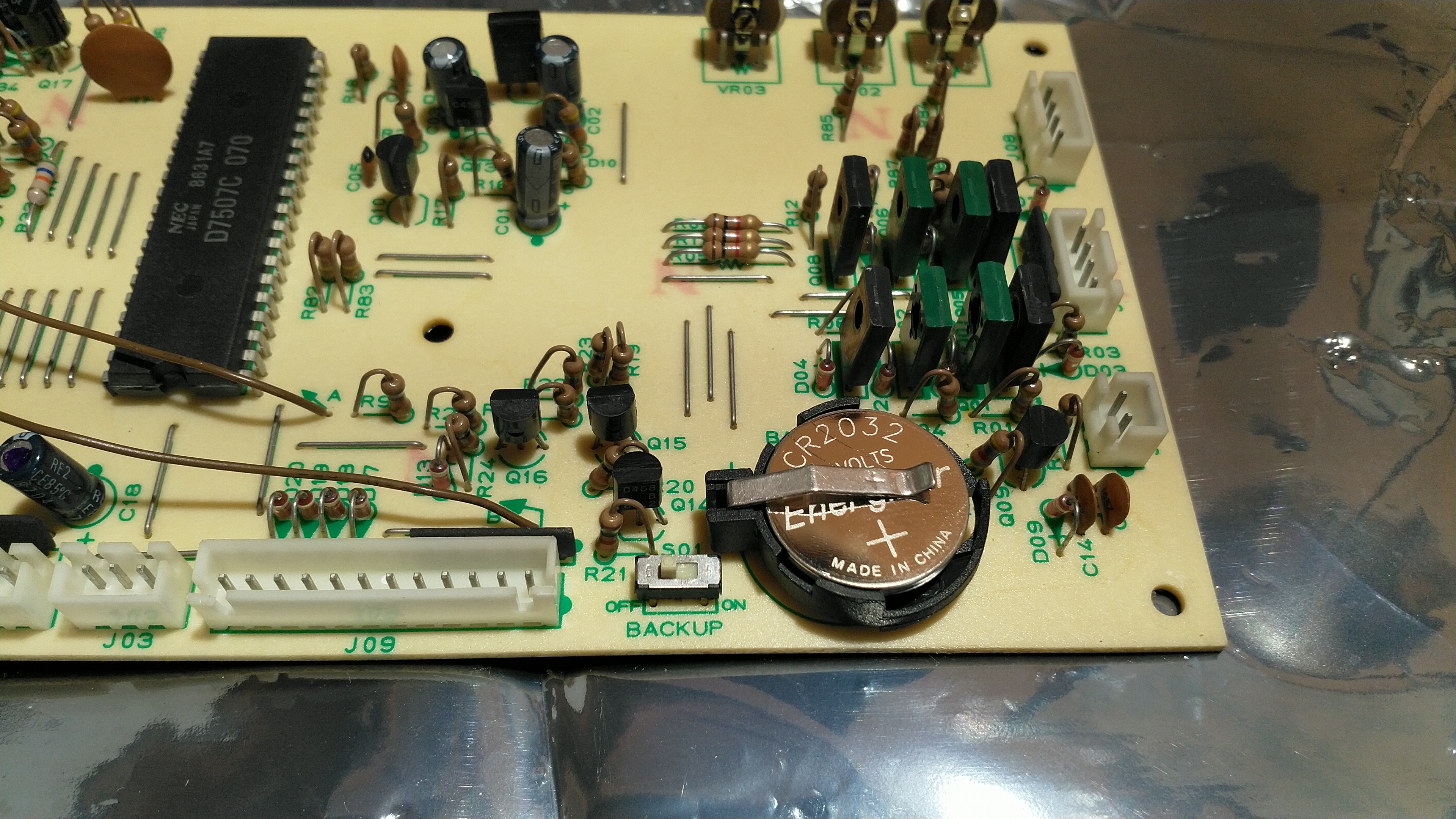
The Aerial Matching Unit lives in the top heat-sink lid. Once removed and opened up, the circuit board can be removed. Take care with the variable capacitors as they are now free-floating. The battery is visible on the circuit board:
Click on the image to load a larger version (in a new window).
Removal of the battery requires a large-tip soldering-iron and good quality de-soldering braid. The tabs are folded over and you may need a scalpel or tweezers, plus the application of the soldering iron, to fold the tabs up enough to facilitate battery removal.
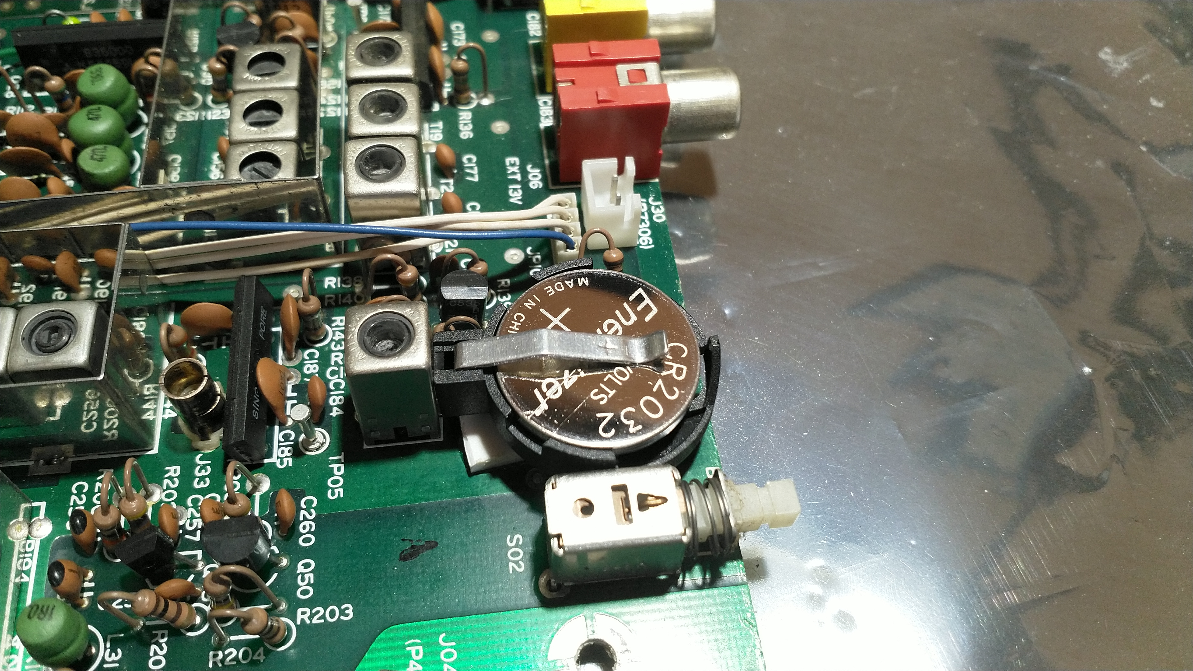
There is space on the circuit board to drill an extra hole to suit the CR2032 coin-cell holder. A 1.2 mm drill hole should suffice. A small area of the solder resist can be scraped away with a small straight-head screwdriver. The image below shows the cell-holder soldered into place, with the extra pin bridged with a small piece of tinned copper wire. Older PCBs do not always clean-up that well and solder can sometimes refuse to flow. A bridge may be ugly, but it helps ensure a good circuit. Excess flux was washed off after.
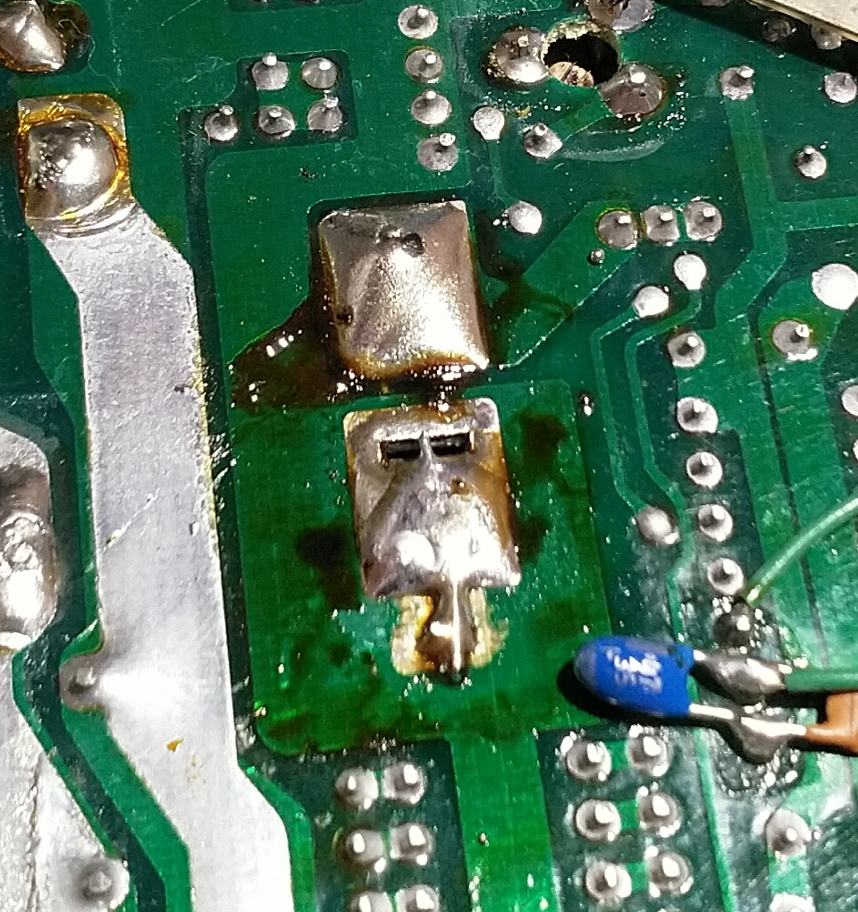
Click on the image to load a larger version (in a new window).
Top-side of the board with the CR2032 installed:
Click on the image to load a larger version (in a new window).
After re-assembly, remember to flip the switch back to ON, else the AMU will have no memory!
Keyer Fault
The FT-767GX also had an odd fault: set CW mode, with no external Morse key attached, press the VOX button, and the radio would switch to transmit. If the monitor function was enabled, a side-tone would be heard if a Morse key (or a blank 6.35 mm jack plug) was inserted. The radio would only switch to receive when the internal keyer was enabled. The internal keyer with an Iambic key would function correctly. A straight key would not.
Diagnosis of the fault: This was a head-scratcher that required checking logic levels (5 or 0 volts) around the keyer chip and the hex inverter package Q60 (MC14049UBCP) on the IF board (underside). Please forgive the shoddy mark-up on the schematic below. The red bridge between the output of one gate on Q60 and the input of another gate on Q60 denotes normal operation when the keyer switch on the front panel is in the out position. Depressing the keyer switch breaks this link.
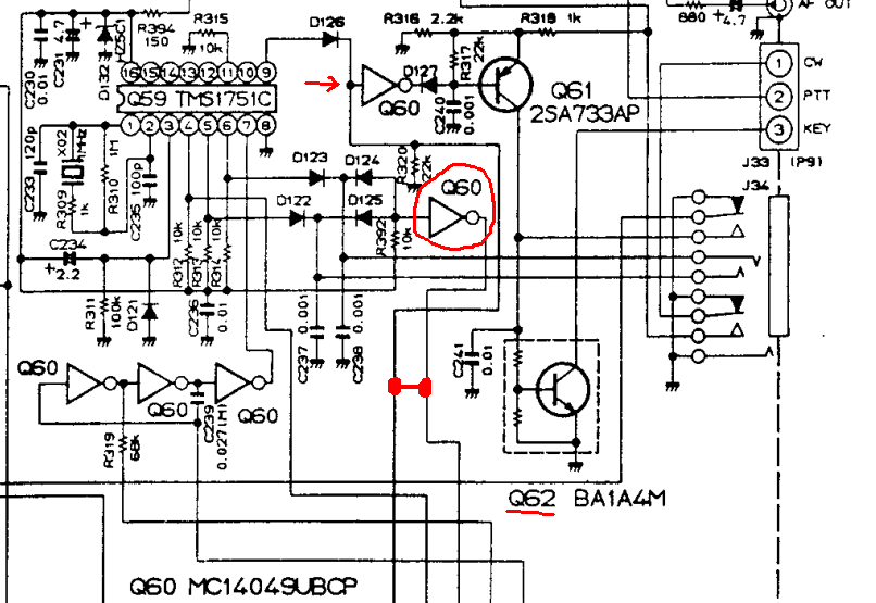
The fault: The input to Q60 on pin 7 had somehow been damaged and was now locked in a low state. R392 (10 k) should pull the input up to 5 volts. D124 and D125 allow a straight key to pull the input down on key-down (D122/D123 feed an Iambic key). With the input to the gate blown and pulling low, the output inverted to a high state. This in turn feeds the next gate (red arrow) which inverts to low, pulling on Q61 to activate Q62. Q62 pulls on the KEY line, which pulls down via the semi/full break-in control, the PTT line. Activating the keyer switch on the front panel broke the link from the faulting gate.
The fix: Cutting pin 6 and 7 of Q60 confirmed that gate was at fault. As the I.F. board is complex and features a lot of connectors, I fitted a 16-pin DIL socket prior to fitting a new MC14049UBCP. Should Q60 suffer damage again, it is a simple task of removing the bottom cover and swapping the chip over.
July 2019 - Yaesu FL-7000
The FL-7000 amplifier, like the FT-767GX above, was part of the local Radio Amateur's shack, and it too had both dead batteries and a couple of faults.
The amplifier is extremely heavy. I recommend working on it on a heavy-duty bench with suitable towels to protect both the bench and the amplifier.
Disassembly is straight-forward. Remove the side plates, followed by the top and bottom covers. The front panel can be rotated, with the removal of three screws (and the loosening of the other two on the side) to gain access to the control board. As above, I recommend photographing things before unplugging.
FL-7000 Faults
There were two major faults with this amplifier, and both are quite common.
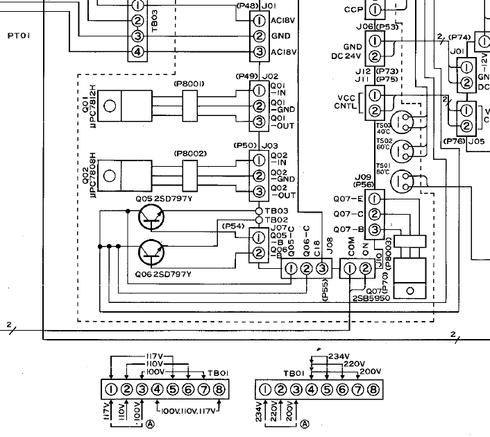
The first major fault was with the power supply. Both TO3 regulator transistors (Q05 and Q06) had failed short-circuit, so instead of supplying 48 Vdc, they were passing over 60. They can be found on the top-most heat-sink and may need to be replaced with modern equivalents. Q07 has also been blown to short-circuit across all pins.
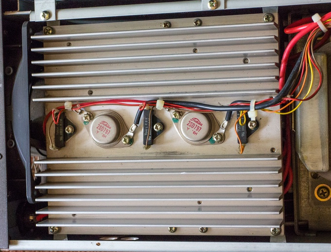
Make a note of the wiring when changing the transistors and refer to the schematic in the FL-7000 manual:
The above fault may or may not have contributed to a failed PA transistor. There are four in this amplifier, set in two blocks with the current phased together to provide up to 600 Watts output. With one of the transistors failing on one of the modules, the combiner circuit detects an imbalance and trips the safety mechanism.
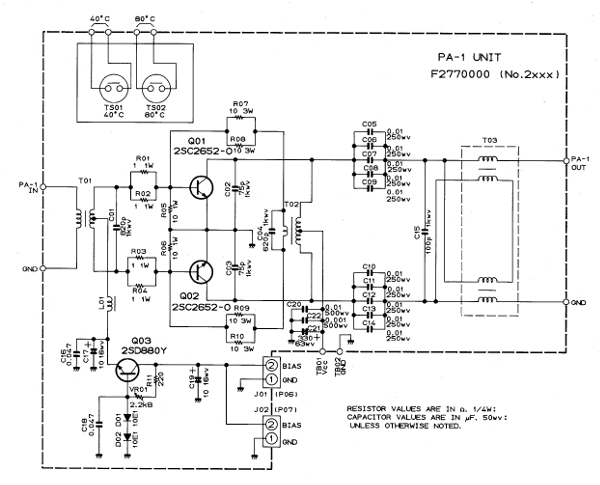
In this design, both transistors operate in pull-pull, or current sink-sink. If one of the transistors has failed, the circuit will be out of balance. In the case of the amplifier I was repairing, Q02 had failed, causing the imbalance trip-out, plus a burn-out of one of its Base bias resistors (R03/R04).
If you have to replace the PA transistors, it is a good idea to replace all four of them. If you can afford it, try sourcing matched pairs, or matched quads in order to minimise any Intermodulation Distortion caused by slight differences in the gains of each transistor. Be aware, these transistors are obsolete and very expensive!
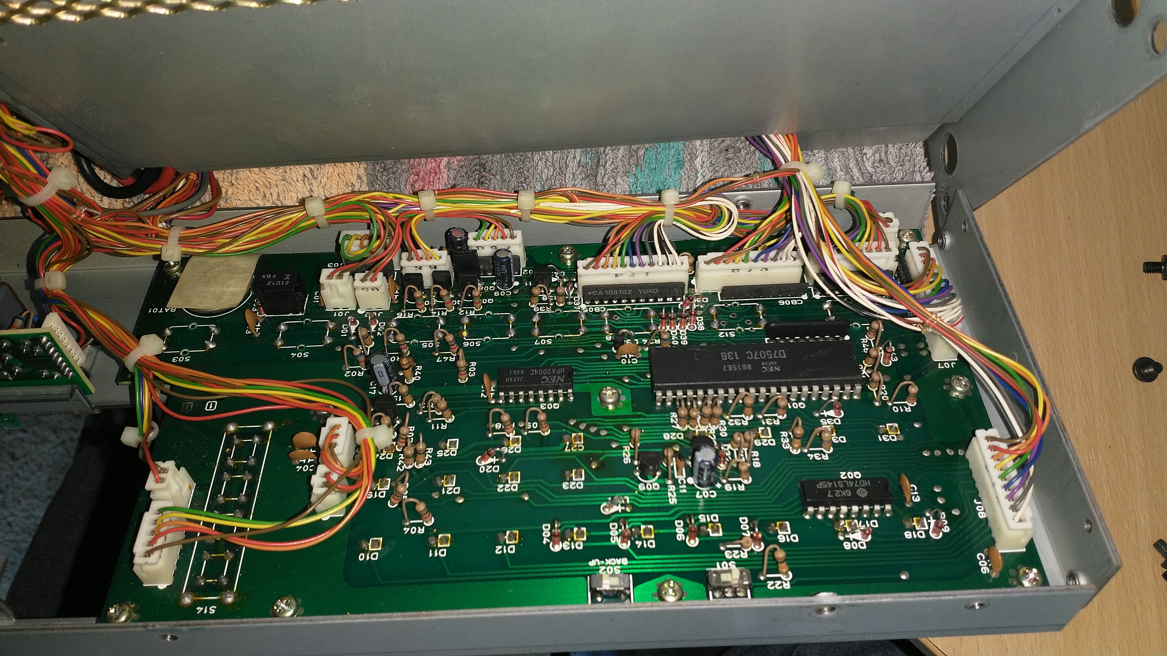
FL-7000 Display board
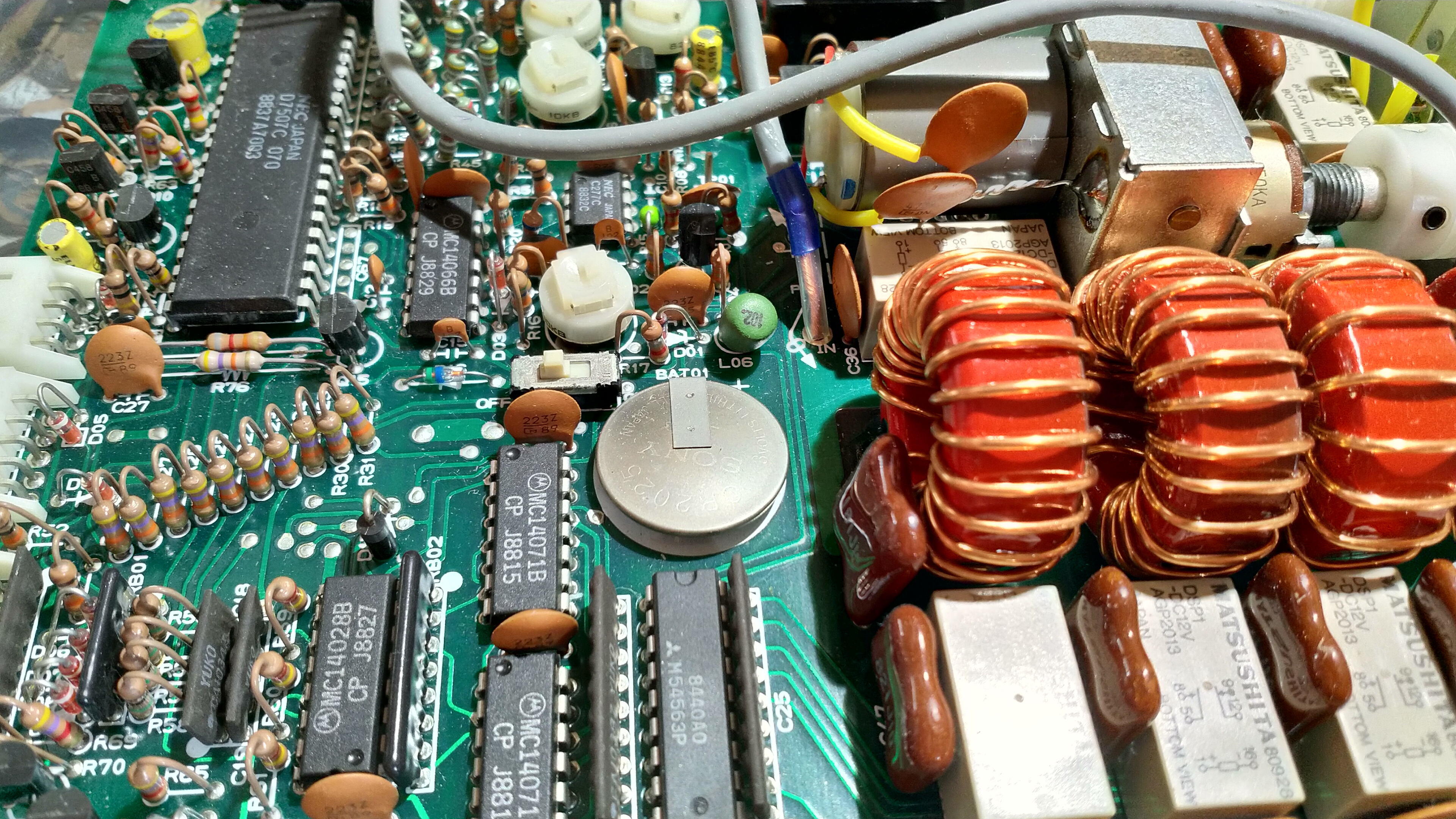
The battery can be seen hiding underneath the beige tape (top left):
Click on the image to load a larger version (in a new window).
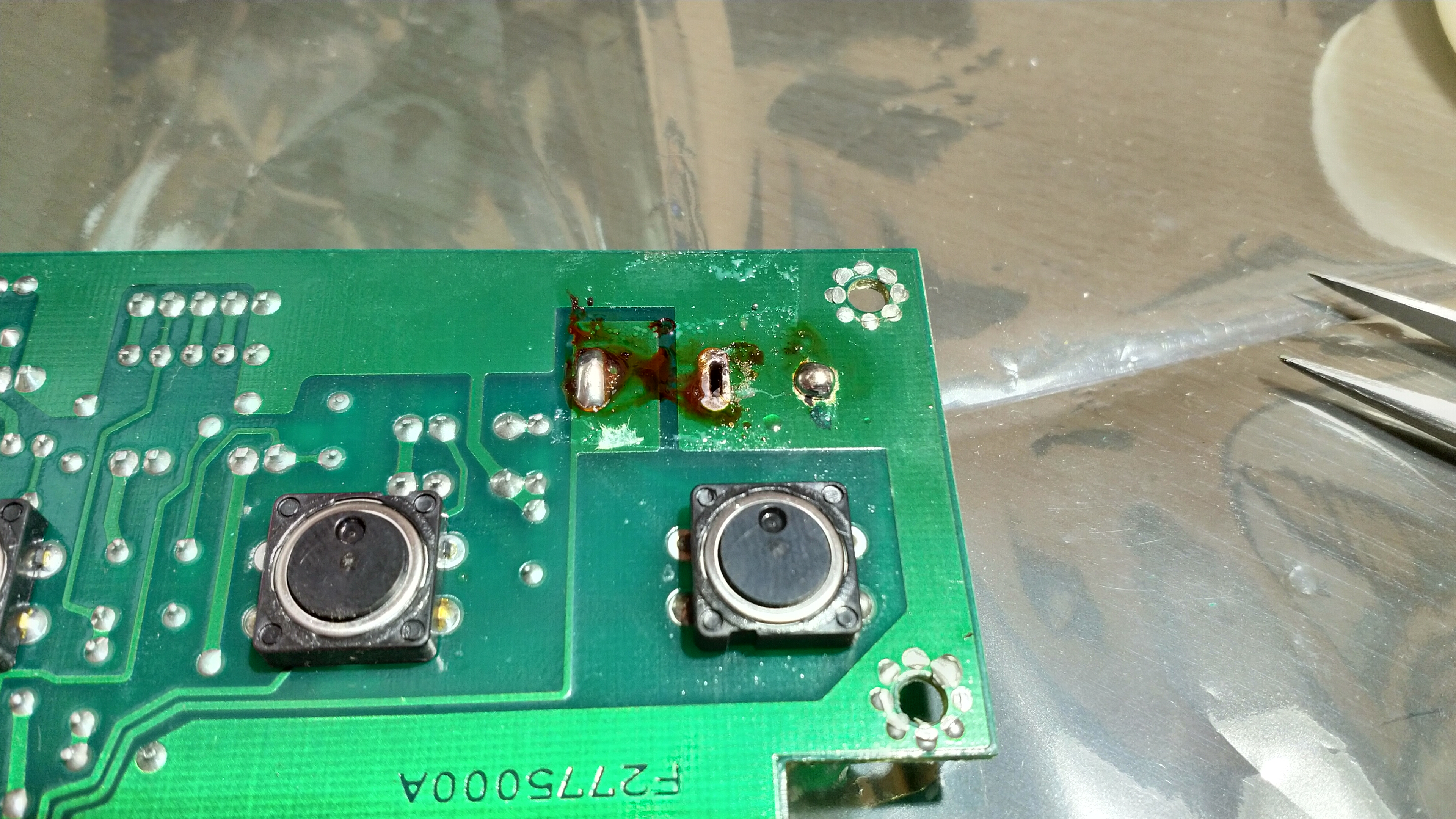
There is space on the circuit board to drill an extra hole to mount a CR2032 coin-cell holder. A 1.2 mm drill hole should suffice. Remove some of the solder resist with a small flat-bladed screwdriver. The next image shows the cell holder soldered with the new hole. Excess flux was cleaned off after.
Click on the image to load a larger version (in a new window).
Top-side with the CR2032 installed:
Click on the image to load a larger version (in a new window).
After re-installation, remember to flip S02 back to ON!
FL-7000 Aerial Matching Unit
The internal Aerial Matching Unit control board also features an on-board battery. Access to this board is a little tricky. Tip the amplifier on its side after removing the AMU cover plate. It should be possible, with a bit of fiddling, to slide the AMU unit out enough to gain access to the control board (note the connectors you have to unplug):

Click on the image to load a larger version (in a new window).
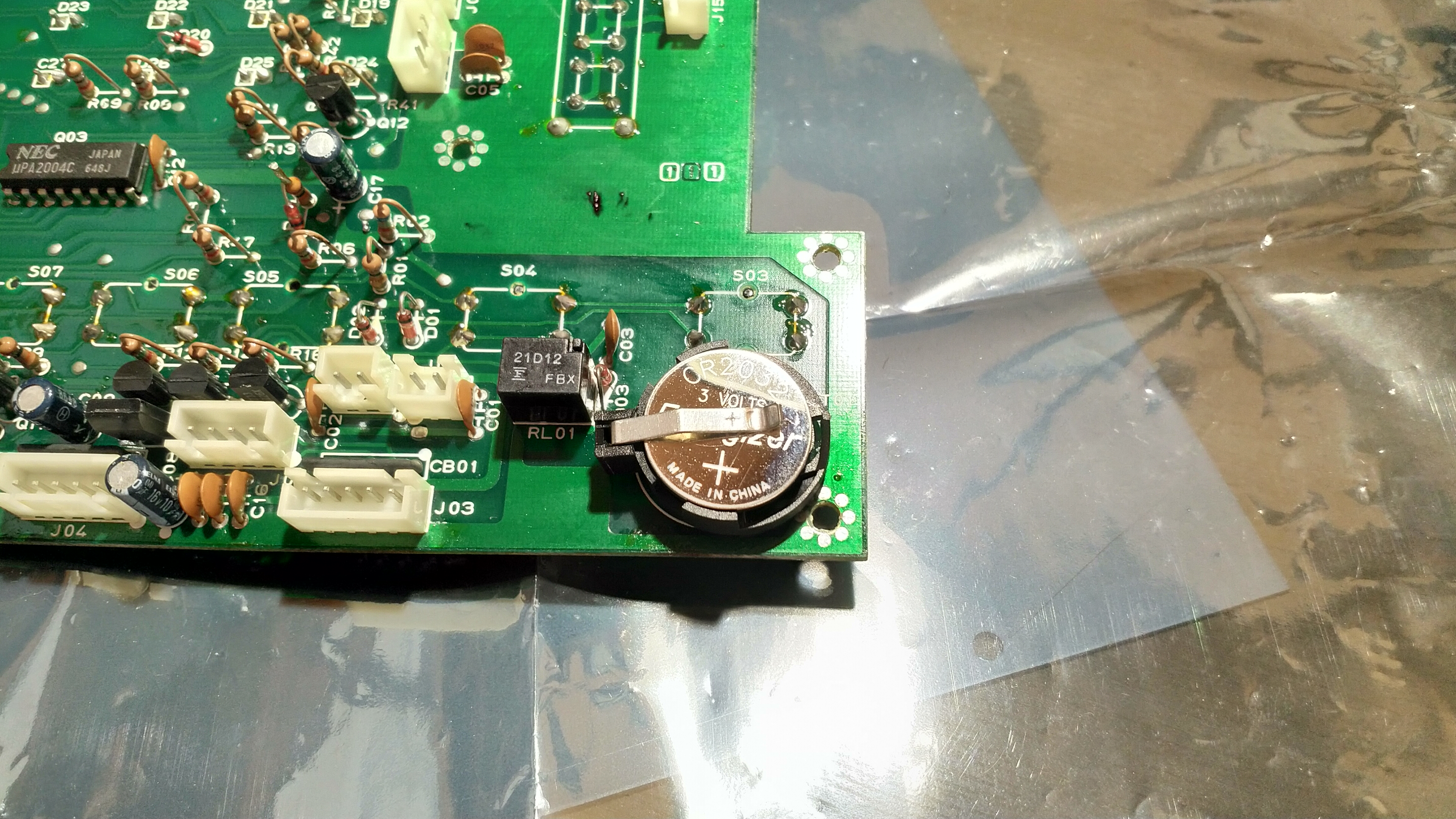
As with the display board above, there is space to drill an extra hole to mount a CR2032 coin-cell holder:
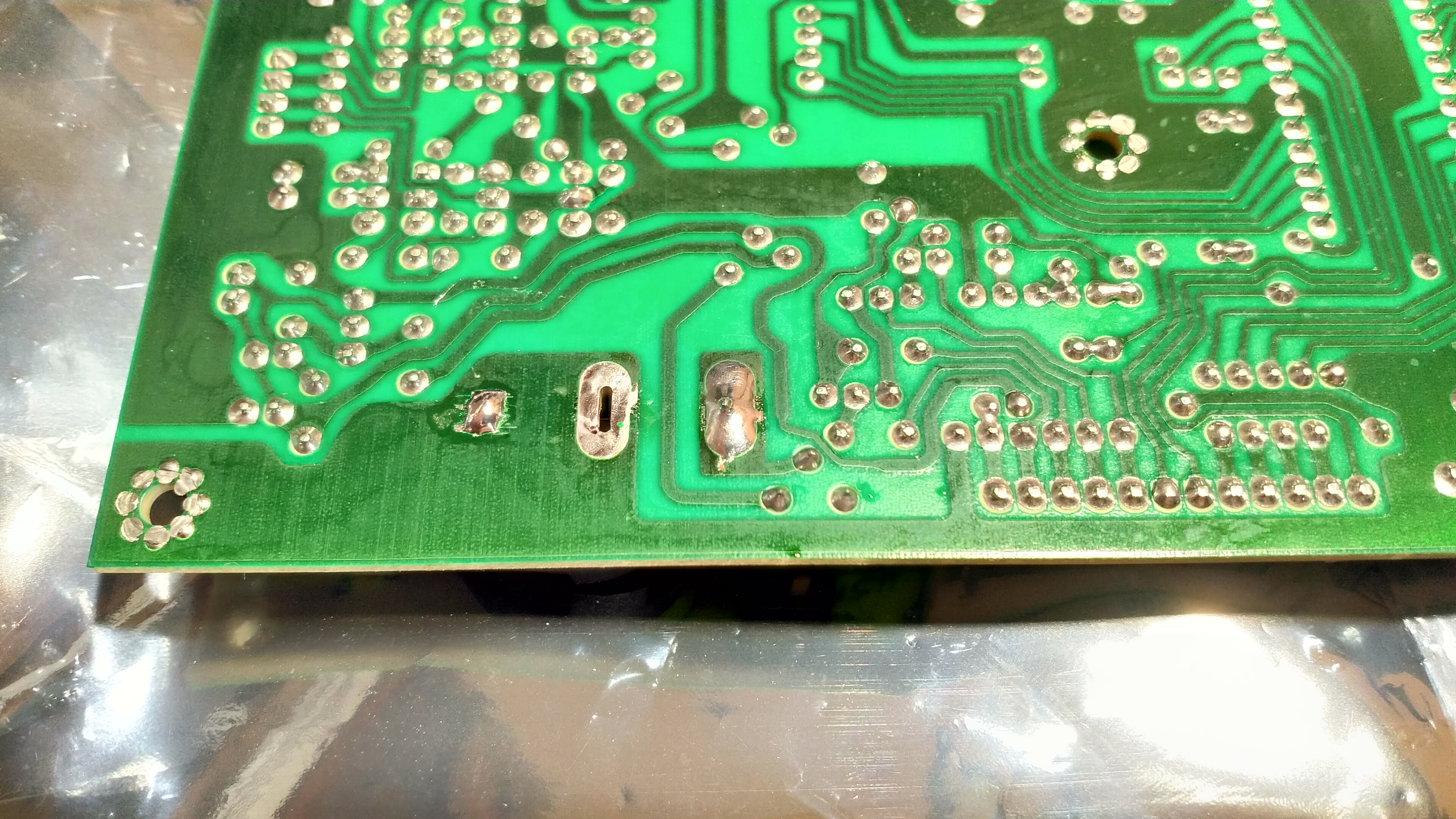
Click on the image to load a larger version (in a new window).
Top-side with the battery installed. Remember to flip the switch to ON after re-assembly.
Click on the image to load a larger version (in a new window).
Page updated: 13th August 2021
Home
|
Tips
|
Awards
|
Linux
|
fldigi
|
APRS
|
QSSTV
|
WSJT-X
|
Projects
|
PSU
|
Repairs
|
Downloads
|
Links
SSTV Gallery
|
eQSL Gallery
|
MQ0PLT eQSL Gallery
|
MQ0PLT eQSL Awards