

Projects :: 4 metre Transverter Mark II
Mark I
The 70 MHz (4 metres) is an odd band. Only 500 kHz wide here in the UK with very few radios or aerials produced to cover it. The choices are pretty slim: super-expensive Japanese radios, in-vehicle PMR, hand-held PMR, or a transverter. I was growing tired of holding a hand-held radio, which I had to modify in order to modulate at a level we Radio Amateurs are used to; and I did not want an FM-only PMR. If only I could use my FT-991A with the Neewer desk mic and the foot switch...
The idea occurred to me to purchase a 4m Transverter Kit. The site appears to have gone offline since the invasion of Ukraine.
An ideal lock-down project that did not require a great deal of assembly. The model I purchased featured a version 2 board with a 42 MHz TCXO, which I
found to be 400 Hz LF and no way to adjust it. Not a huge problem for FM nets - I simply added 400 Hz to the memories I stored in the FT-991A.
The transverter lasted three days before I forgot to turn the transmit power down. It took another three days to get rid of the smell; and I had to
revert to the hand-held! If you are new to Amateur Radio, or electronics in general, and are curious as to how the Magic Smoke™ smells,
may I suggest wafting a bottle of  TCP antiseptic
under your nose? Burnt electronics has a similar smell - something you will no doubt experience in your projects! People have often looked at me
with a somewhat confused expression when they present me with faulty electronics ... and the first thing I do is smell it. As an Electronics Engineer,
I know only too well the smell of failure!
TCP antiseptic
under your nose? Burnt electronics has a similar smell - something you will no doubt experience in your projects! People have often looked at me
with a somewhat confused expression when they present me with faulty electronics ... and the first thing I do is smell it. As an Electronics Engineer,
I know only too well the smell of failure!
The attenuator board bought it after dumping 100 watts into it! This photo is after I had peeled the burned-out resistors off what was left of the tracking; and tested my new hot-air rework station on one of the resistors.
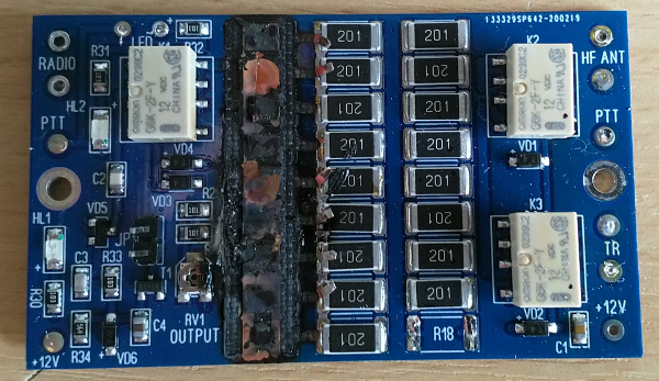
My fellow hams on the net commiserated me and said I was not the first person to blow-up a transverter. I vowed to make another with a protection system to cut the power if the idiot driving the radio forgot to turn things down!
Mark II
The Mark II 70 MHz transverter would be bigger (I wanted to use SO-239 and N-types) and better. It needed an "Idiot Circuit" to protect the insides from the idiot driving the radio. Apply too much power, and the "Idiot Circuit" would trip, light a bright LED, sound an alarm, and shut-down the transmit power from the FT-991A. How to go about all of this?
The FT-991A (and other Yaesu models) feature an 8-pin mini-DIN which you use to connect to external equipment, like a linear amplifier, or the FC-40 remote long-wire matching unit. I have the latter on the rear of my shed, connected via approx. 20 metres of exterior-grade Cat 6 (plus RG213 for the RF, of course). This is certainly not recommended by Yaesu, but it works rather well for my set-up. I already had an 8-pin mini-DIN lead running to an RJ45, which plugs-in to a standard Cat6 socket, then on to a similar system in a small box on the rear of the shed. Several of the pins on the mini-DIN could be made use of for the transverter.
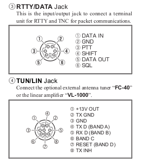
Pin 1 provides +13 volts from the radio - ideal to power some small relays (not to be used for high-current applications). Pin 2 is switched to ground on transmit - ideal to create a buffered PTT function for both the front mic and the internal CAT control. Pin 8, when taken high (connected back to pin 1) cuts the transmit power from the PA stage. Pin 3 gives us a ground; the remaining can simply loop through.
It was off to ebay to source suitable bits to assist in creating the Mark II.
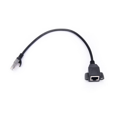
I found this RF-45 extension cable with a panel mount socket on one end and thought two would be ideal for the loop-through function. They are available with a variety of descriptions: "RJ45 Male to Female Screw Panel Mount Ethernet LAN Network Extension Cable". I looked for 8-pin mini-DIN solutions, but they all required some sort of PCB layout that was going to add to the complications. Likewise for PCB-mounted RJ-45 sockets. With the panel-mount solution, one simply needs to snip-off the RJ45 plug and strip the insulation back.
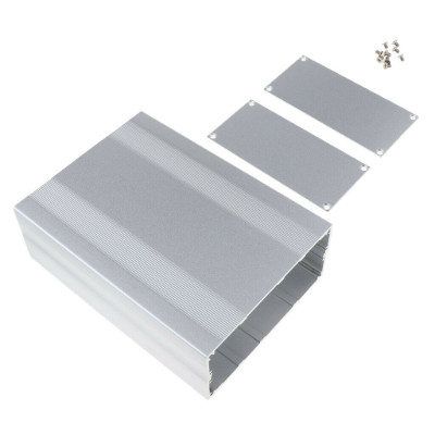
Next up was a suitably sized box. I found this "Extruded Aluminium Enclosure Cooling Flat Box Case DIY 200x145x68mm -Silver" and ordered one from a Hong Kong supplier.
I also ordered new transverter and attenuator boards from the
Transverter Store
in case I had destroyed the transverter board when running too much power.
ProgRock
I am something of a frequency purist. I have a Meinberg M600 GPS/NTP server, and I like to be spot-on frequency. The 400 Hz offset was bugging
me, and I wanted a better solution. The
ProgRock Kit,
a triple-output, GPS-disciplined programmable crystal was just the ticket. As I have a Pulse-Per-Second available from the Meinberg M600,
I did not need a super-accurate TCXO as I could discipline the clock from GPS and the 42 MHz output set on CLK0 would always be spot-on.
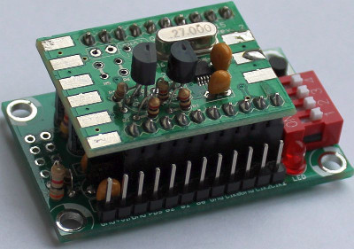
The ProgRock is a nice little kit to build. Take note of the instructions. The LM317 should be fitted to the controller board - not the synth board - if you want to run the ProgRock from an external source greater than 5 volts. I used the DIP switches and my memory of BCD to set two frequencies: 42 MHz on CLK0 and 3600 Hz on CLK1. The latter will be explained later. The output is a 3.3 volts square-wave, so I asked a fellow ham if he had the time to make me a low-pass-filter. His construction can be seen in the pictures below.
Idiot Circuit
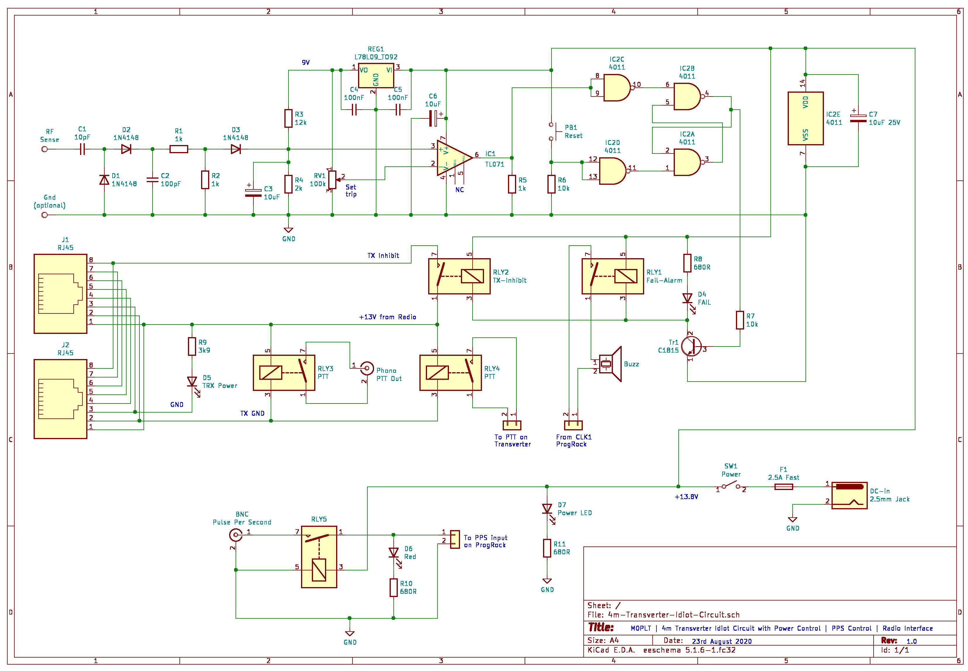
With a new attenuator board, it was now time to develop the "Idiot Circuit" that would protect the transverter from over-driving the input power. The circuit would need to achieve several things: sense the RF input and generate a voltage; trigger a comparator to signal over-power; and flip a set-reset latch to the fail state, which in turn would shut-down the power from the radio. The circuit detailed below was the end-result of the development:
Click on the image to load a larger version (in a new window).
The schematic above was drawn-up in
KiCAD
after I learned the gEDA project is orphaned and most of the Linux distributions are dropping it.
How does it work?
The RF sense input is connected to the radio-input side of the [transverter] attenuator board. On my version, I attached a wire to the input of relay K2. C1, D1, D2, and C2 provide a DC conversion of the 28 MHz RF signal. At this point, the voltage can be as high as 30 volts, even with only 5 watts input. This is too high to use, so I drop that with the potential divider of R1 and R2. Without input RF, this point is at zero volts, and the comparator cannot work this way when you are using a single-volt rail. R3 and R4 provide a "bias" voltage to work against. The voltage presented via D3 increases this bias when RF is present. C3 was needed to provide a transient block. The comparator was triggering on transmit even with only 5 watts set. The value of 10uF was an arbitrary choice. Too small and there is no protection from the transient. Too high, and it takes too long to charge, so an over-power event cannot be detected quickly enough.
The comparator trip-level is set via RV1 - a multi-turn potentiometer. RV1, R3 and R4 are fed via a fixed 9 Volt regulator to ensure variations in the supply voltage do not inadvertently cause a false trigger, or fail to trigger. 9 volts was chosen as I had a spare 78L09. 10 volts would also suffice; especially if, like me, you have the facility to run from a large deep-cycle battery. C4 and C5 provide decoupling to avoid RF leakage causing the regulator to go into parasitic oscillation. C6 provides RF decoupling for the Op-Amp. I used a TL071 as I had these in stock. A standard 741 would also suffice. C6 and onwards should all be rated at 25 volts. The trip-level is configured by setting 10 watts on the radio, then adjusting RV1 until the SR-latch switches state. In practice, I found the trip would activate with 8 watts and higher.
The output of the Op-Amp is pulled low via R5 to avoid a false trigger of the SR-latch. The set-reset latch is made with a CMOS quad 2-input NAND chip. Two of the gates are wired to provide inverting buffers as this prevents noise from falsely triggering the latch - an issue with CMOS! C7 provides decoupling. A "high" state signal from the Op-Amp is inverted via the first gate. This flips the second set of gates that are wired to provide a latching flip-flop. This state will be retained until the Op-Amp output goes low, and the reset button (PB1) is pushed (pulling the gate input high). In the "fail" state, pin 4 of the 4011 switches on Tr1 via the base-current limiting resistor R7. The transistor used was a C1815 - again, because I had spares. Any NPN transistor that can sink 100mA would suffice. RLY1 and RLY2 are MEDER SIL relays, part number: SIL12-1A72-71D. Not shown in the schematic, these relays have built-in diodes to suppress back-EMF. They have a + mark on the case so you wire them up correctly. Also activated by Tr1 is a bright yellow LED, limited to around 20mA by R8.
In the fail state, RLY1 connects the CLK1 output from the ProgRock board, which is set at 3600 Hz (lowest I could set mine to), to a PCB-mount buzzer. It is not very loud, but sufficiently annoying to attract one's attention. The development circuit featured a 555 timer configured to buzz until I realised there was a spare output on the ProgRock. RLY2 takes the +13 volts from the FT-991A and feeds it back to the transmit-inhibit line on pin 8. To keep things simple, the 8-pin mini-DIN lead I made has a 1-1 pin-out with the mini-DIN and the RJ45. The transmit-inhibit disables any RF power from the PA stage - even if you keep your finger/foot on the PTT.
In operation, the fail mode appears to be the default from power-up. I thought this annoying at first, then I realised it was quite handy to check that the SR-latch was actually doing its job. The 3600 Hz tone also indicates the ProgRock board is alive.
Other features!
R9 and D5 provide indication on the front panel that the radio is powered-up and connected. R9 is a 3k9 as I started with a green LED and a 680R resistor. You could see the green LED from space, so I changed the limiting resistor. You could still see it from several kilometres away so I changed it for a blue LED. Modern LEDs can be a little bright! RLY3 and RLY4 are the same MEDER SIL relays with diodes. They provide a PTT buffer function from the radio, with RLY3 providing a PPT out on the rear panel, and RLY4 providing the PTT function for the transverter boards. The attenuator board provides an RF sense PTT function. Remember to remove the jumper if you are going to use a direct PTT control.
Also featured, using another MEDER SIL relay, is a control to switch off the Pulse-Per-Second signal when the transverter is powered down. This was a late addition after finding the PPS signal, all 2.5 volts of it, was leaking through the ProgRock back into the supply rails. The leakage caused a number of the LEDs to pulse as modern LEDs seem to light up with very little current. RLY5 simply provides isolation. There may be a better way of achieving this, such as using an opto-isolator, but I only had relays in stock.
Pictures
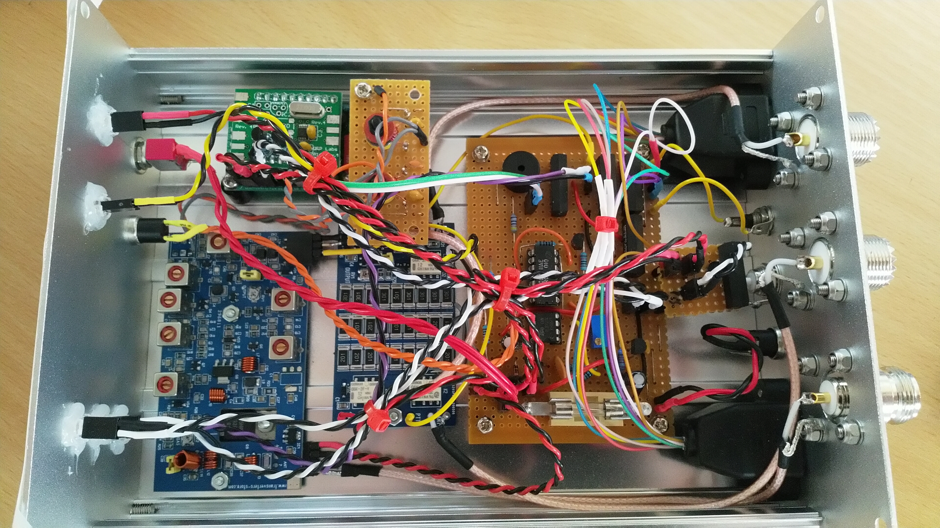
Here is a top-view of the insides. Top-left is the ProgRock board with the low pass filter kindly made for me by
Chris G3XIZ.
Bottom-left is the 70 MHz transverter board. This was the original TCXO version board. I had managed to avoid blowing it up,
so I lifted the TCXO and its voltage regulator, then fed the 42 MHz signal in place of the original oscillator. Buried in the middle
is the attenuator board. Sitting behind that is the Vero board containing the "Idiot Circuit", the PTT relays, fuse and
power feeds, plus connections for the Pulse Per Second. All of the LEDs are connected via 2.54mm pin-headers - just in case any fail.
The white heat-shrink on the four floating wires had to be fitted after my first idea of using IPC crimps failed and the external
FC-40 refused to talk. The wires were originally under the board. They are now floating as I could not put them back under once
soldered. I had thought about soldering them in the first place, and took a short-cut, which did not work!
Click on the image to load a larger version (in a new window).
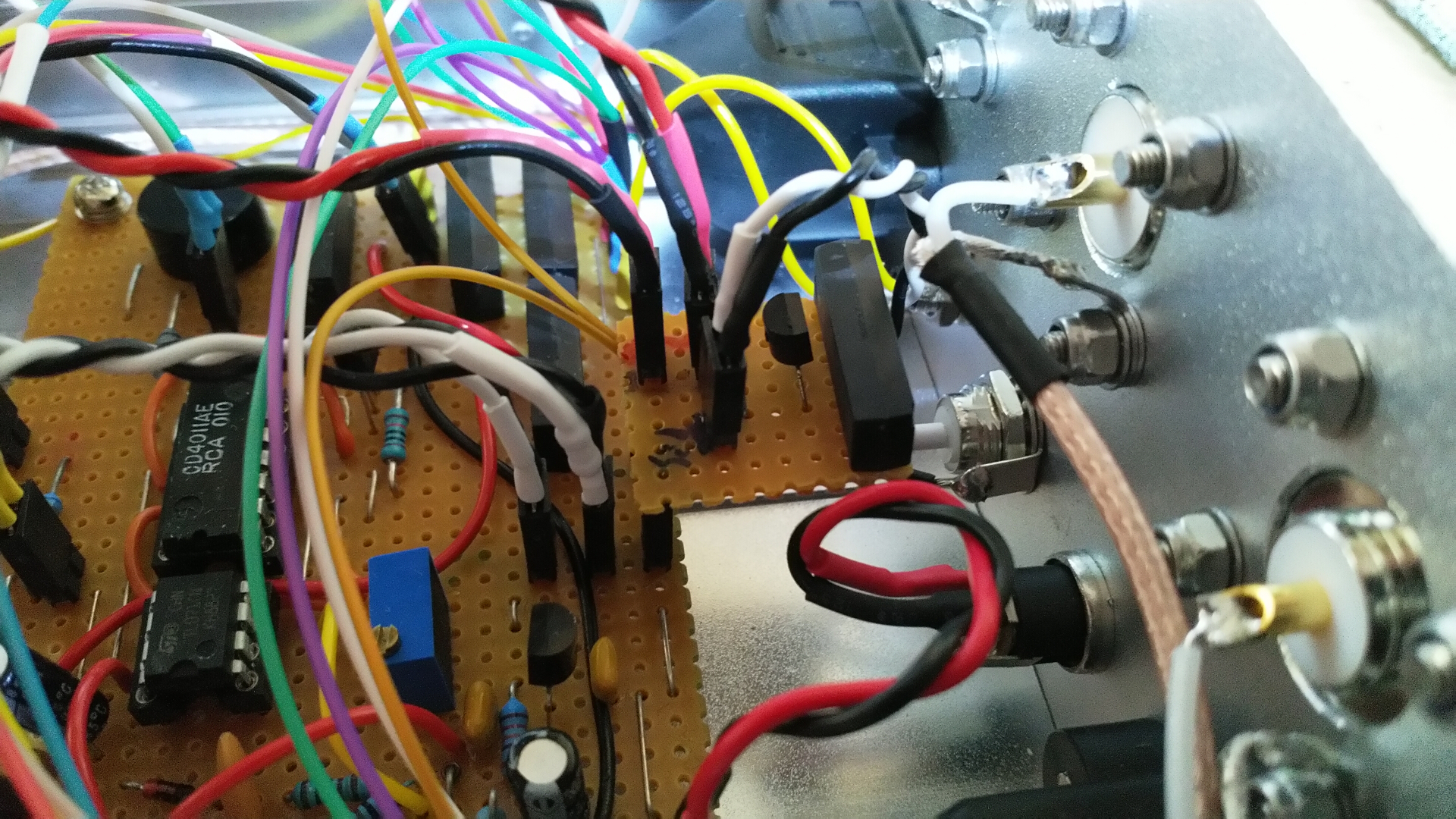
There was no room to add the relay for the PPS isolation, so I made a little daughter board, looping the power for the main LED through two pin headers. I only had 5V versions of the MEDER relays left, so I added a 78L05 to power it. I also decided to add a limiting resistor to the front panel red PPS LED. I did not leave myself room on the Vero, so it ended-up in the lead covered with heat-shrink. The same thing happened with the TRX power LED. That is what you get for building something at midnight!
Click on the image to load a larger version (in a new window).
Here are all of the rear connectors:
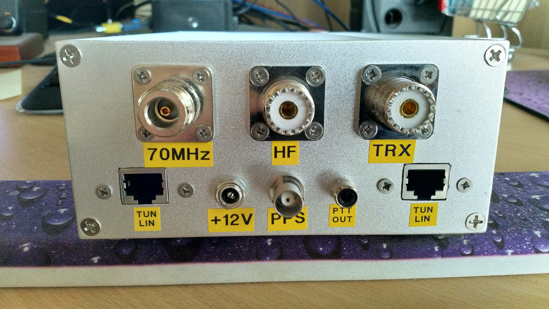
Click on the image to load a larger version (in a new window).
So I am not going to win any awards for the rear panel markings! How about the front panel?
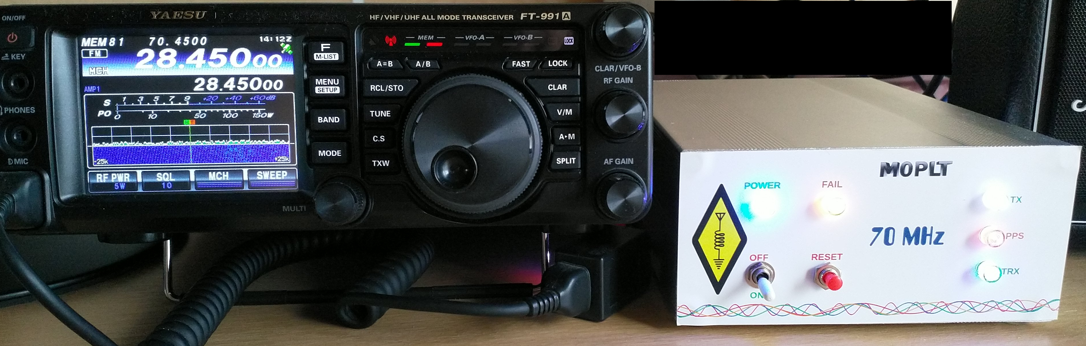
Click on the image to load a larger version (in a new window).
The camera on my Nokia 8 struggled a little with the LEDs. The POWER LED is a colour-changing version that slowly cycles through a variety of colours. The FAIL LED is yellow; the TX LED is white; the PPS LED is red; and the TRX LED is blue. You might notice from the FT-991A's display that the fail mode is preventing any transmit power from being delivered. The label was created in LibreOffice Draw and printed on Avery L7068 polyester heavy duty laser labels. There are two per A4 sheet, so it is a little wasteful. The label was affixed and cut-down to suit the aluminium panel. The bulges in the corner are due to the countersunk screws not quite sinking flush. I neglected to check this before making-up the front panel!
In conclusion
This has been a worthwhile project as I can now take part in the local 4 metre nets using the exceptional audio quality of the Neewer desk microphone and the FT-991A; and be totally lazy with my foot-switch for hands-free operation. I have limited the transverter board to deliver 10 watts, which is sufficient for local rag-chews; and possibly some FT8 when conditions permit. I may yet experiment with C4FM and SSTV on 4 metres...
Of course, once you build something like this, you immediately want to re-design it. An output power/VSWR meter would be nice; as would a properly designed PCB. That would probably require a bigger box!
Page updated: 29nd December 2025
Home
|
Tips
|
Awards
|
Linux
|
fldigi
|
APRS
|
QSSTV
|
WSJT-X
|
Projects
|
PSU
|
Repairs
|
Downloads
|
Links
SSTV Gallery
|
eQSL Gallery
|
MQ0PLT eQSL Gallery
|
MQ0PLT eQSL Awards