

Projects :: Variable dummy load
Most Radio Amateurs have a standard 50 Ohm dummy load that can handle at least 100 Watts to aid in their set-up and testing. If you end up servicing Amateur Radio transceivers, you may come across the need to present up to three dummy-loads in parallel. The SWR turn-down setting in many transceivers can only be set effectively with a 16.67 Ohm load connected. This replicates a 3:1 VSWR, and most radio manuals will instruct the service engineer to reduce the transmit power to 90 Watts (for a 100W system) in order to protect the power-amplifier transistors.
If you need to make this adjustment, or test aerial matching units, you either have to own three 50 Ohm dummy loads that you can plumb in parallel with RF adapters, or you have to make a variable-load box. This is how I made mine.
Shopping list
I sourced three 50 Ohm microwave resistors capable of handling 150 Watts from a well-known tat-bazaar. They will likely be 'used' so
be careful with your construction, and watch for damage. The resistors usually contain
 Beryllium Oxide, which can be nasty stuff, so handle your resistors carefully!
A double-pole, double-throw, centre-off switch capable of handling 5 Amps (or more). If you are going to build a variload to handle 1000 Watts, you will want to check how much current the switch needs to handle!
A suitable aluminium box.
A suitable aluminium heat-sink. Its size depends on how much energy you plan to dissipate.
An RF connector of your choice, although I seriously recommend sticking with N-type, and adapting as required.
Nuts and bolts as needed. If your heat-sink is chunky enough, and you have a tap/die set, you can always cut threads into the heat-sink to avoid the need to position fiddly nuts and washers.
A generous squirt of heat transfer compound.
Here is one I made earlier!
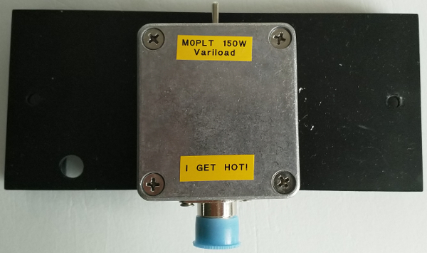
My thanks to Chris G3XIZ for the donor heat-sink. So what is inside?
Click on the image to load a larger version (in a new window).
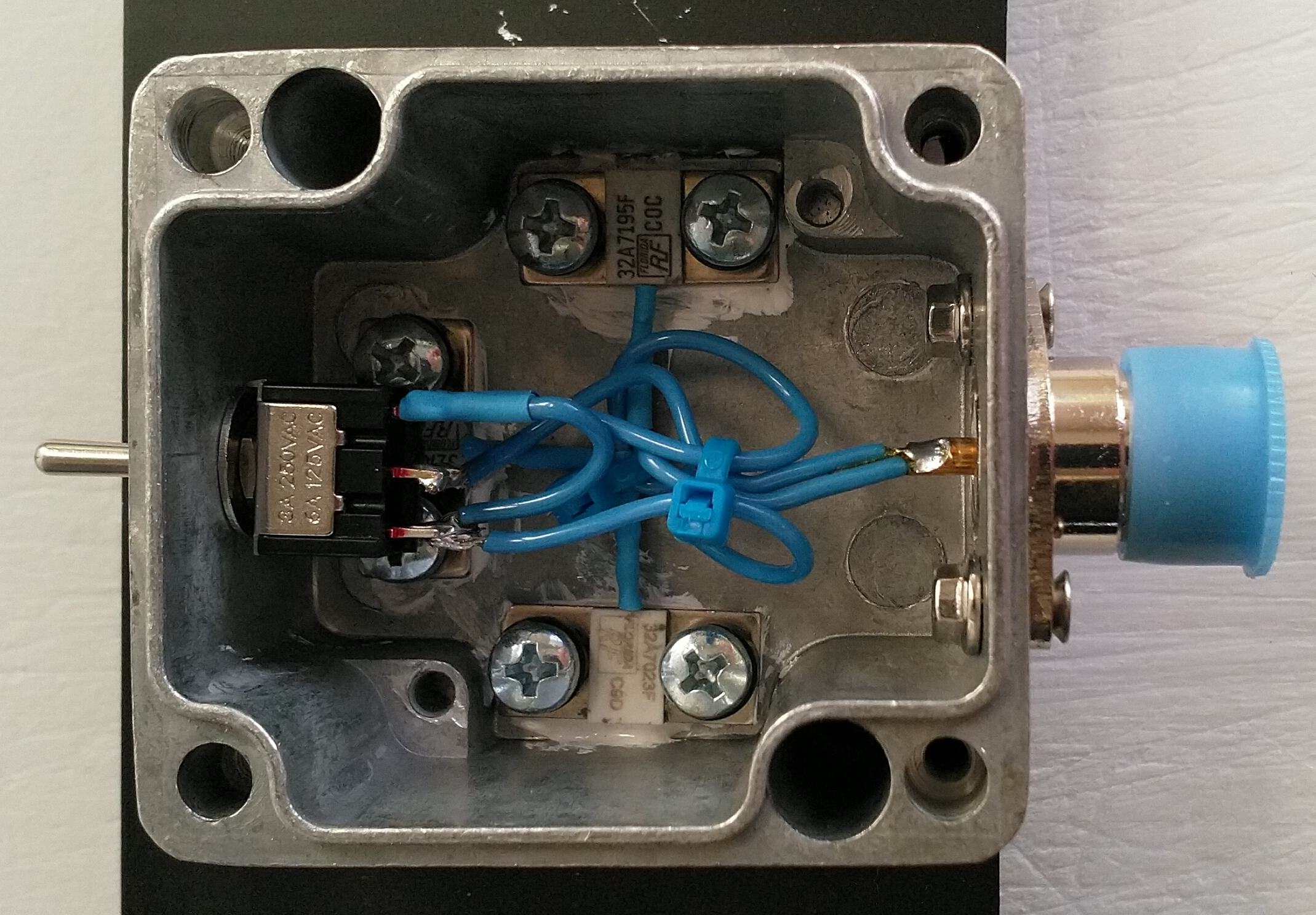
The three resistors are held-down with M4 screws. As the heads were a little too large and risked damaging the resistors, I added some spare hard plastic spacers. I was using-up spares, so my choice of screws was a little limited. M3 screws may have been a better choice. The holes through the main box were drilled at 4.5mm to provide a clear path and a little wiggle room. The holes in the heat-sink were drilled to 3.5mm, then tapped-out with an M4 tap. Ideally you should use a 3.8mm drill, but I do not have one. Take care when tapping to use a nice drop of machine oil to prevent the aluminium from fouling the tap. You can easily make a mess of your threads! Resistors and box have a healthy amount of heat transfer compound spread between them to help transfer the energy to the heat-sink. Tip: add the transfer compound only when you are completely ready to assemble.
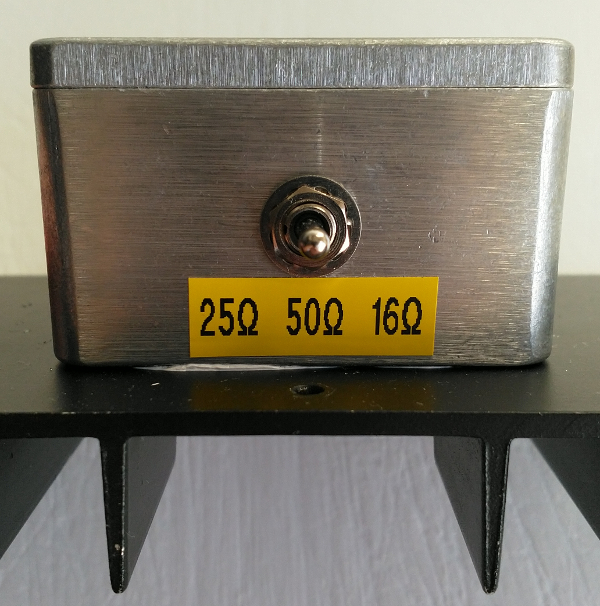
How does it work? In the centre-off position, one 50 Ohm resistor is always presented to the N-type connector. Click the toggle switch to the left and a second 50 Ohm resistor is added in parallel to produce 25 Ohms. Back through the off position, and a click to the right and all three 50 Ohm resistors are now in parallel to produce 16.67 Ohms. Of course, the tolerances on the resistors means you never see exactly what the mathematics suggests.
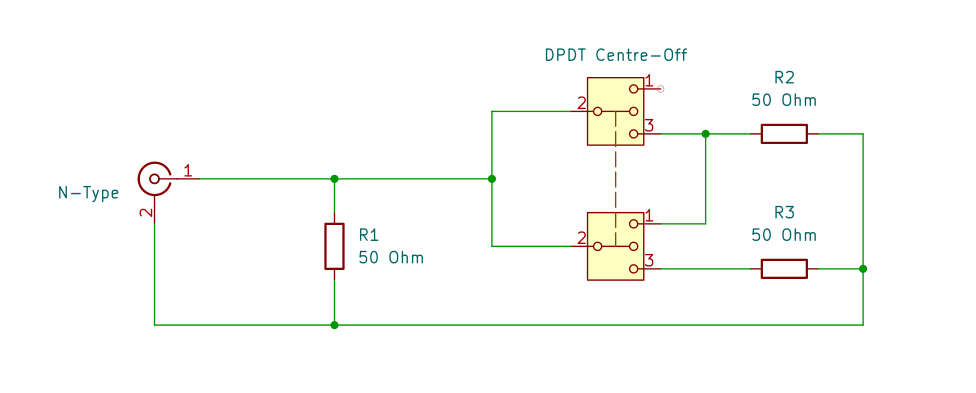
The first 50 Ohm resistor and the input from the N-type are wired to the centre of the DPDT centre-off toggle. Here is a schematic to help you wire your own:
Click on the image to load a larger version (in a new window).
This has been made for the 'test-equipment' box. I would add a much larger heat-sink if I was going to use this for long periods.
Page updated: 15th October 2025
Home
|
Tips
|
Awards
|
Linux
|
fldigi
|
APRS
|
QSSTV
|
WSJT-X
|
Projects
|
PSU
|
Repairs
|
Downloads
|
Links
SSTV Gallery
|
eQSL Gallery
|
MQ0PLT eQSL Gallery
|
MQ0PLT eQSL Awards