
Projects :: RSSI meter
12 LED Calibrated RSSI Meter
Signal meters have always been a funny thing. ITU-R define S9 as -73dBm in a 50 Ohm system. So is your S9 the same as my S9? My first job as a Test Technician taught me how to calibrate the company's products against our NAMAS traceable test-equipment. If you ask me about an S-meter, I will have to respond with "Indicative use only!". That is the sticker you will find on any equipment that is out of calibration. Why indicative? As I have found over the years, setting S9 against -73dBm on various CBs and Amateur rigs does not mean the other S-points will be accurate.
A few years ago, my CB of choice was the Intek M-495 Power, and I operated one in the home and one in the car. The inclusion of
CTCSS (although technically not legal to use in the UK on the CB frequencies) was a useful way of driving the squelch in a world
with increasing interference (QRM) from the noise-sources listed on the
 UKQRM website ... as long as the
other people you are talking to had a CB with CTCSS! The external S-meter socket offered a chance for experimentation.
With an RF signal generator, I set about recording the output voltages against the ITU-R levels for S1, S2, et al, up
to S9+30. The results, once fed into LibreOffice, produced an interesting graph.
UKQRM website ... as long as the
other people you are talking to had a CB with CTCSS! The external S-meter socket offered a chance for experimentation.
With an RF signal generator, I set about recording the output voltages against the ITU-R levels for S1, S2, et al, up
to S9+30. The results, once fed into LibreOffice, produced an interesting graph.
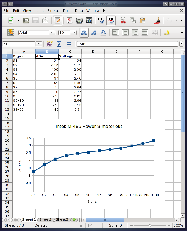
The RSSI response of the receiver-chain was non-linear. Of course, this revelation only came about after I had experimented with little RSSI circuits based around the LM3914/LM3915/LM3916 bargraph drivers. I took inspiration from their internals and set about designing a larger system of comparators that could have their switch-over levels independently set.
I came up with the following design based around three TL074 quad Op-amp chips used as comparators.
Update 29th November 2020: Re-drawn in KiCAD!
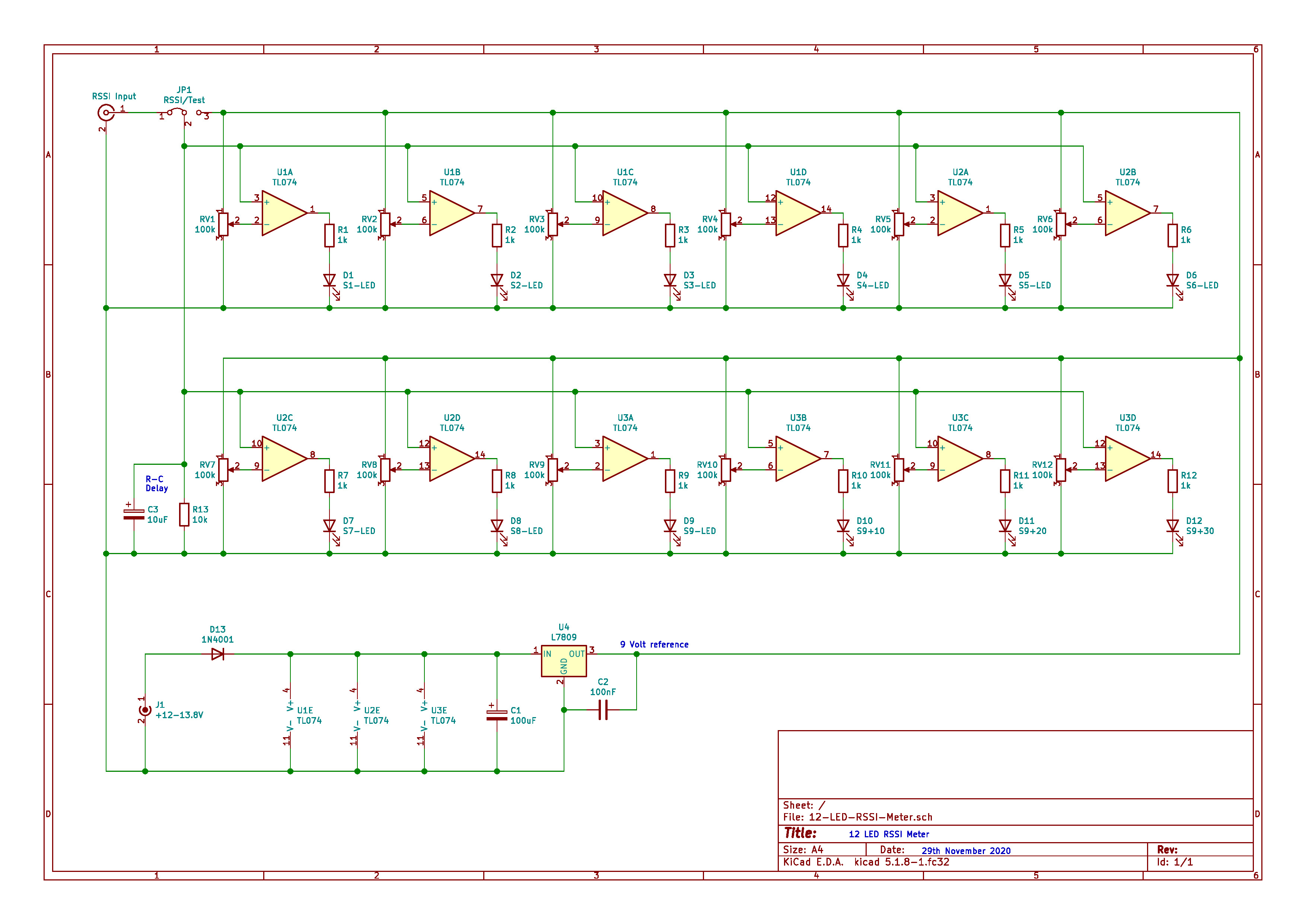
Click on the image to load a larger version (in a new window).
The above is revision 1.1 of the design. The first version did not feature the 9V regulator and I found, when operating from a battery, that the drop in supply voltage affected the comparator switching levels. The 9V regulator provides a fixed reference voltage to 'calibrate' against. The 10k (R13) and 10uF (C3) capacitor/resistor combination provide a delay circuit and remove any noise/strobing effects from the received signal. The 1k dropping resistors for the LEDs are an arbitary value. Adjust them to suit the brightness of the LEDs you are using.
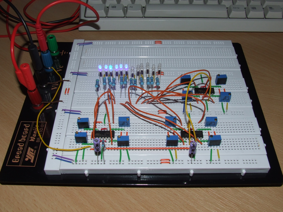
I built the first version on plug-board to prove the concept worked. One of the 'banana' plugs on the left is being fed by the external-meter connector on the Intek M-495. Click on the image for a larger version.
I set about designing a printed-circuit-board to produce two main boards and two display boards from one piece of pre-sensitised copper-clad fibreglass board. The layout was designed to fit inside a certain sized plastic box. If I was to create a new version, I would set the LEDs on the main board and use a better box.
With the PCBs made, I set-out a kit of parts. Click on the image for a larger version.
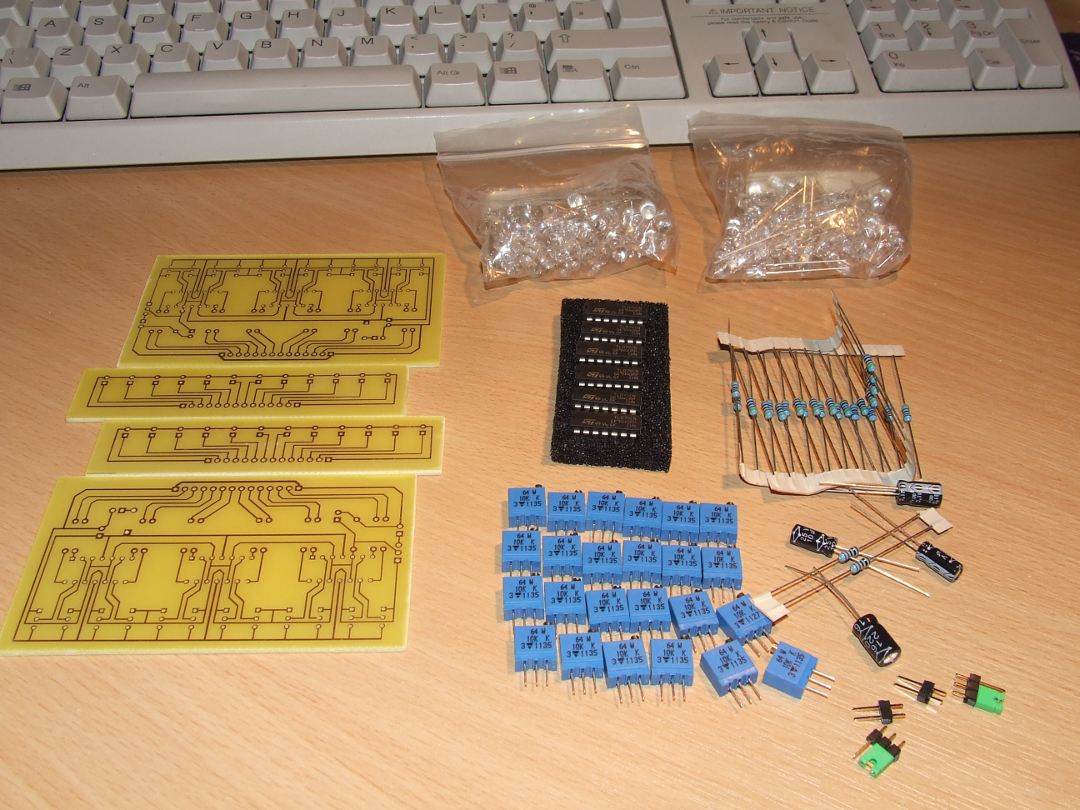
Observant viewers may notice this design does not feature the voltage regulator from the schematic. These were version 1.0 designs that showed-up the issue once in service. They had the 3-pin regulator added later. After modification, all 12 of the potentiometers had to be re-calibrated.
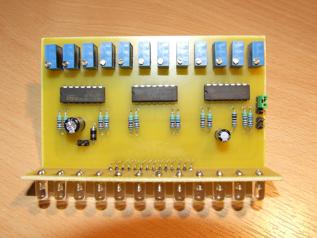
Here is a completed board. Using up spare 20cd blue, white, and 12cd red LEDs required the use of 4k7 current limiting resistors to ensure I did not go blind! Click on the image for a larger version.
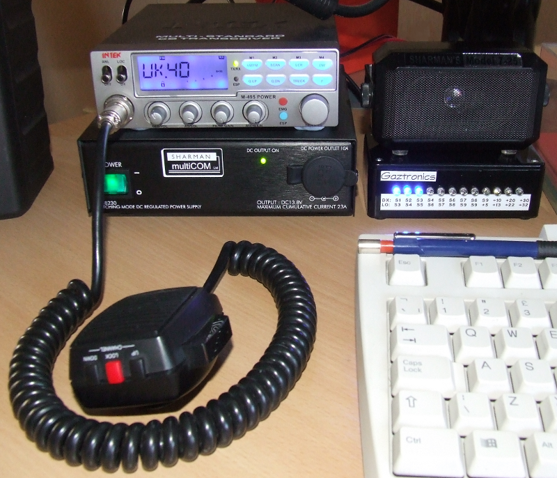
And here is one of the completed RSSI meters providing a 'calibrated' signal level for the Intek M-495 CB. The two levels on the "calibrated tape" (as a friend called it) correspond to the DX/LOC switch position on the radio.
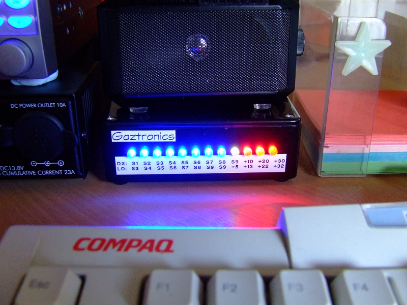
And here it is with a very strong local signal.
The meters are currently not in use as I no longer have a Citizens' Band radio; and my Yaesu FT-991A has a computer driven display. You may wish to build your own to accompany any transceiver that provides an RSSI output.
Download
Please feel free to download the KiCAD schematic to edit for yourself. (Right-click and select Save-as if your browser is trying to be too helpful!)
Page updated: 29th November 2020
Home
|
Tips
|
Awards
|
Linux
|
fldigi
|
APRS
|
QSSTV
|
WSJT-X
|
Projects
|
PSU
|
Repairs
|
Downloads
|
Links
SSTV Gallery
|
eQSL Gallery
|
MQ0PLT eQSL Gallery
|
MQ0PLT eQSL Awards