

Projects :: Knight Rider LED scanner
How about a non-radio project for the fun of it? I created this circuit some years ago, neglected to document it (or did, and lost it), vaguely remembered it, then wondered why, during a recent sort of my electronic spares, I had a 74LS93 and a 74LS154 in stock. I remembered after downloading the datasheets, that I had gone to the trouble of creating a scanning array of eight LEDs to match the scanner in the front of K.I.T.T. So here it is if you want to build and experiment with your own.

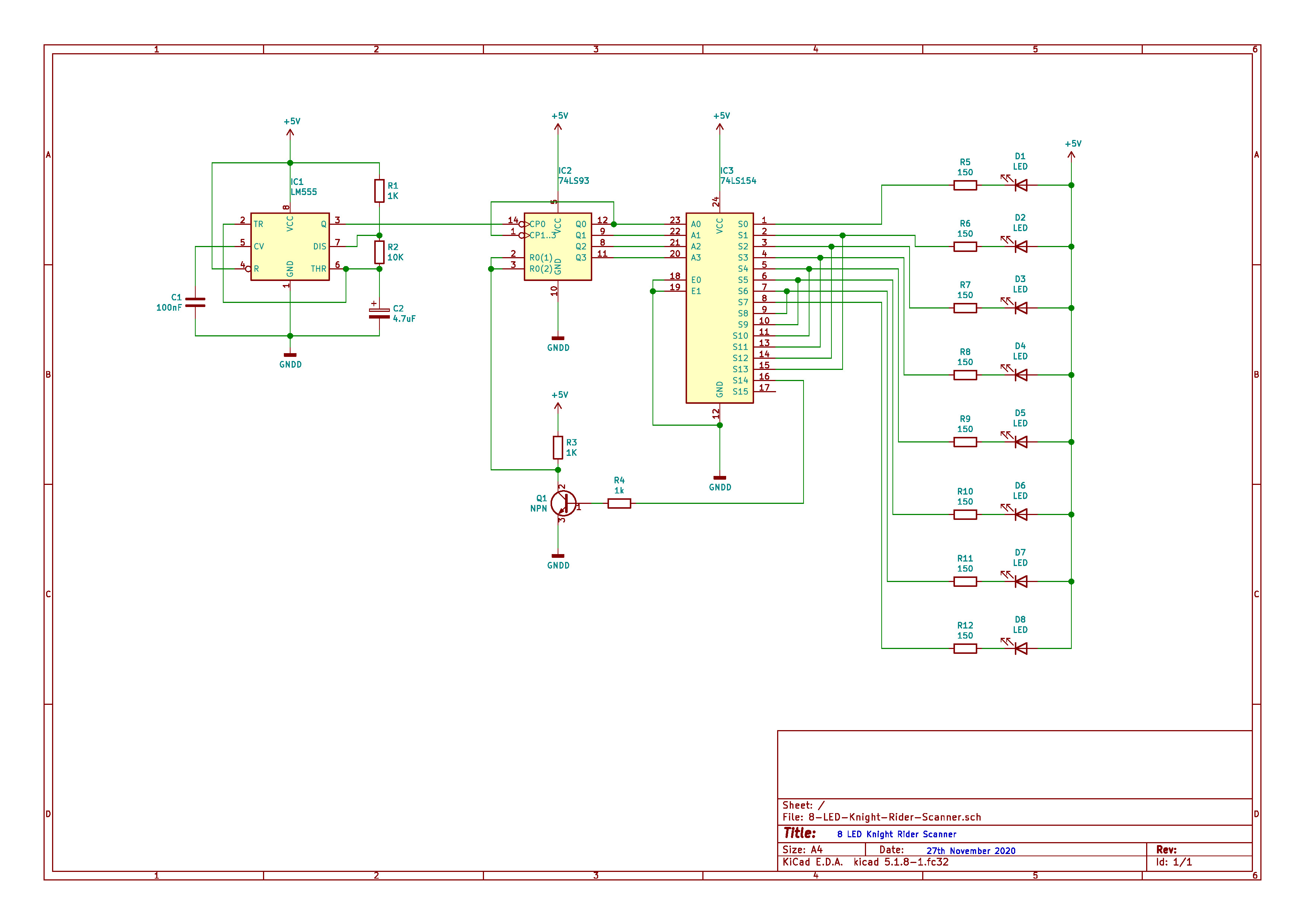
Circuit layout
Click on the image to load a larger version (in a new window).
How does it work?
Top-left is a 555 timer roughly configured to produce a clock-pulse that produces a nice sweep. Other timer methods are available and I will leave it to the reader to experiment with their own, and maybe one that can be varied.
The 73LS93 is configured as a  Binary Coded Decimal
counter. It starts at 0000 and counts up to 1111 with each clock-pulse from the 555. Pins 2 and 3 need to be pulled low for the counter to work.
Taking them high resets to 0000. That feature is used later.
Binary Coded Decimal
counter. It starts at 0000 and counts up to 1111 with each clock-pulse from the 555. Pins 2 and 3 need to be pulled low for the counter to work.
Taking them high resets to 0000. That feature is used later.
The 74LS154 (CD4514BE is the CMOS equivalent) is a BCD to 16-line decoder. All 16 outputs are inverted (open-collector), so you have to configure your LED to sink (fed from the +5 volt rail) in order to see the output "1" on each line. This also makes things easier to create the sweep as output 9 is connected to 7, 10 to 6, and so-on. We do not need the full count to S15 (1111) in order to create the full sweep, so output S14 is inverted via the NPN transistor to reset the 74LS93 counter to 0000. The 150R limiting resistors will drop 3 volts to leave 2 volts at 20 milli-amps for a standard Red LED. You can decrease the value if you want to use 3.5 volt Blue/White LEDs at full current.
The whole thing is powered by 5 volts and uses little current.
Note 1: If you plan to make this in CMOS, you will need to buffer the outputs of the CD4514 as CMOS cannot handle the same amount of current as TTL.
Note 2: You will not be able to achieve the glow delay effect as on the original K.I.T.T. as this used lamps. You could beef this design with high-current transistor switches to power 12 volt vehicle lamps. A reminder to UK readers: The Road Vehicle Lighting Act prohibits the installation of flashing lights on ordinary vehicles, and red lights at the front are a definite no!
Download
Please feel free to download the KiCAD schematic to edit for yourself. (Right-click and select Save-as if your browser is trying to be too helpful!)
Page updated: 28th November 2020
Home
|
Tips
|
Awards
|
Linux
|
fldigi
|
APRS
|
QSSTV
|
WSJT-X
|
Projects
|
PSU
|
Repairs
|
Downloads
|
Links
SSTV Gallery
|
eQSL Gallery
|
MQ0PLT eQSL Gallery
|
MQ0PLT eQSL Awards