
Projects :: GPS Receiver
Intro
A huge thanks to ReiLabs for the information on how to  configure a NEO-6
GPS receiver module. The information would prove very useful for this project.
configure a NEO-6
GPS receiver module. The information would prove very useful for this project.
I came across a fellow Radio Amateur with an older FTM-400 that experienced issues with receiving GPS, and this led to a lack of location data for APRS and C4FM. The later FTM-400XD models contain a more sensitive GPS receiver and do not suffer from signal loss - even inside of a house (unless you have modern foil-coated insulation). I wondered if it was possible to create an external GPS receiver that would interface to the FTM-400 or the FT-991(A).
Since starting this project, the Radio Amateur in question has re-arranged their shack, and their FTM-400 now has a clearer view and a stable GPS lock.
I have experimented with the NEO GPS receivers on Meshtastic devices. They happily work together as they use the same voltage levels. I quickly hit a "gotcha" when trying to talk to a NEO-6 module with standard RS-232. The voltage levels are limited to 3.3 volts, so they are not compatible with standard RS-232 and you simply see garbage. The 3.3 volts data stream must be buffered to/from standard RS-232 with an external MAX2323 chip.
There are several options for RS-232 converter boards available from a multitude of on-line sellers. After trying with a simple surface-mount board, I switched to one with a 9-way D-type as it was easier to interface to.
There is an issue of providing 5 volts for the two boards used in this project. As pin 9 is un-used on the board, I ran a simple 1N4007 (as it was in stock) - to provide reverse-polarity protection - to the input of a TO92 case LM7805 voltage regulator. I added a small electrolytic capacitor to the incoming supply on pin 9 for smoothing. The output and the ground from the regulator are soldered to the VCC and GND pins of the board, as in this photo (with hot-melt glue providing some rigidity).
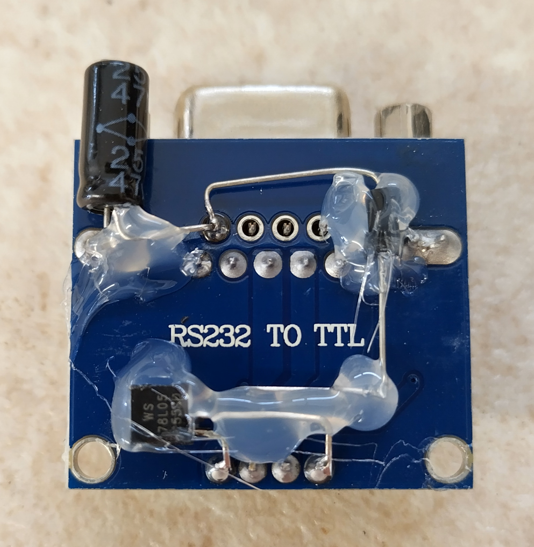
Click on the image to load a larger version (in a new window).
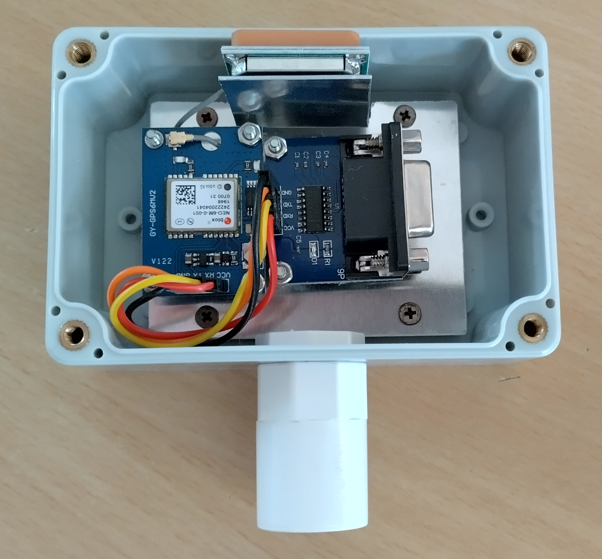
I made a 1 mm thick Aluminium plate to fit inside an IP68 plastic case. The plate holds the GPS aerial, the NEO-6 receiver and the RS-232 converter. M2.5 screws, nuts, and stand-offs were used to hold everything in place. The end of the RS-232 board floats as there are no extra mounting spaces.
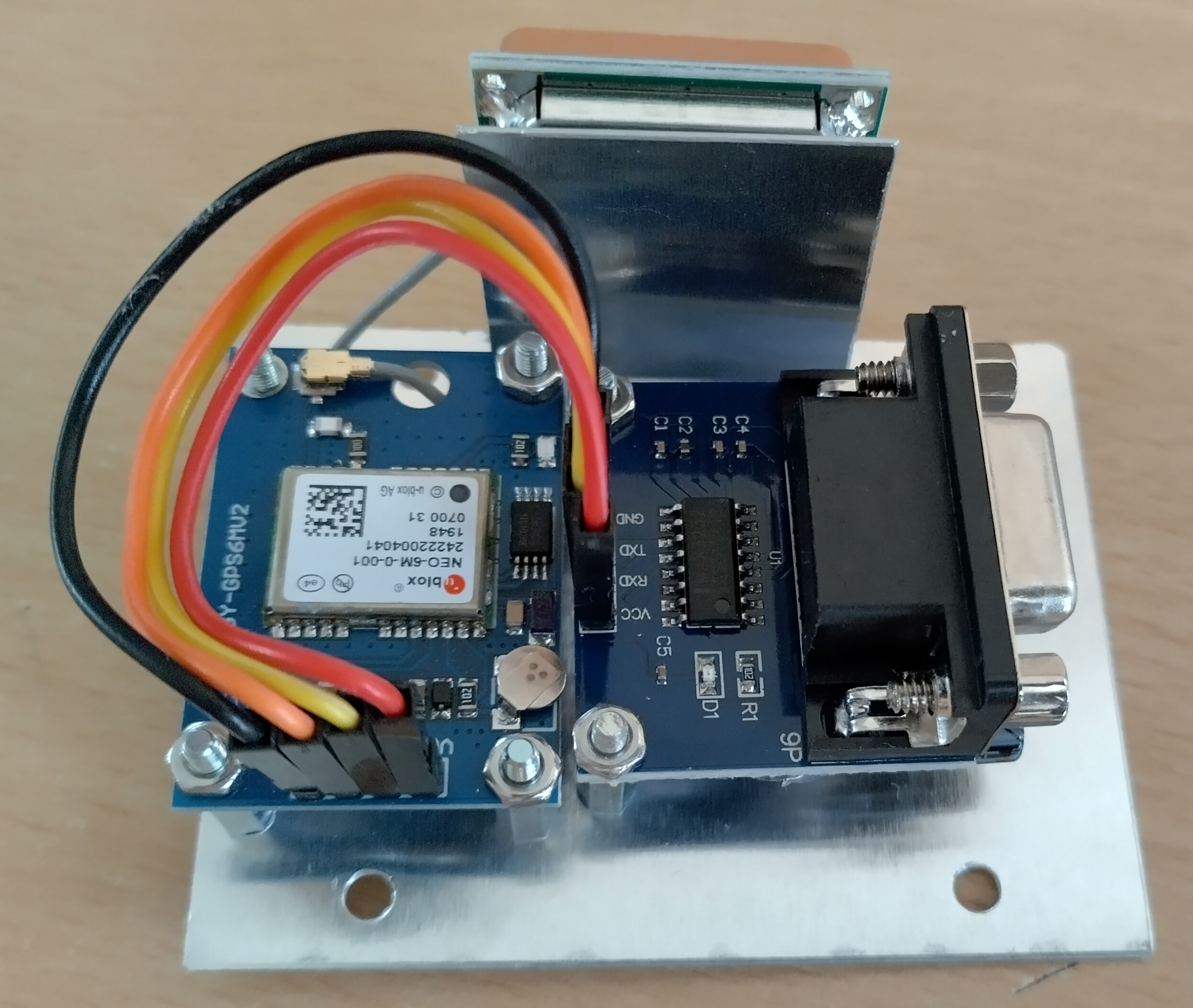
Click on the image to load a larger version (in a new window).
Here is a top-side view:
Click on the image to load a larger version (in a new window).
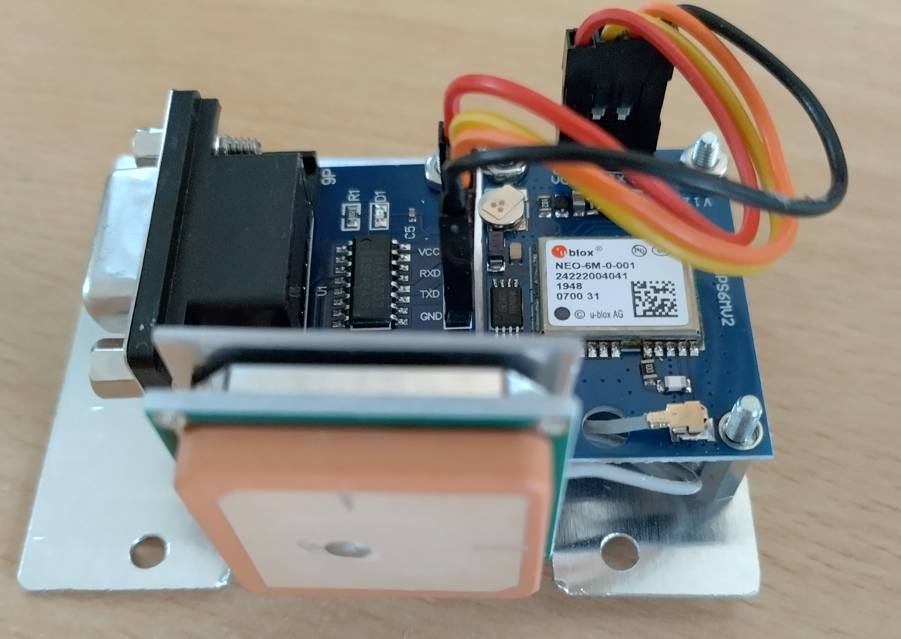
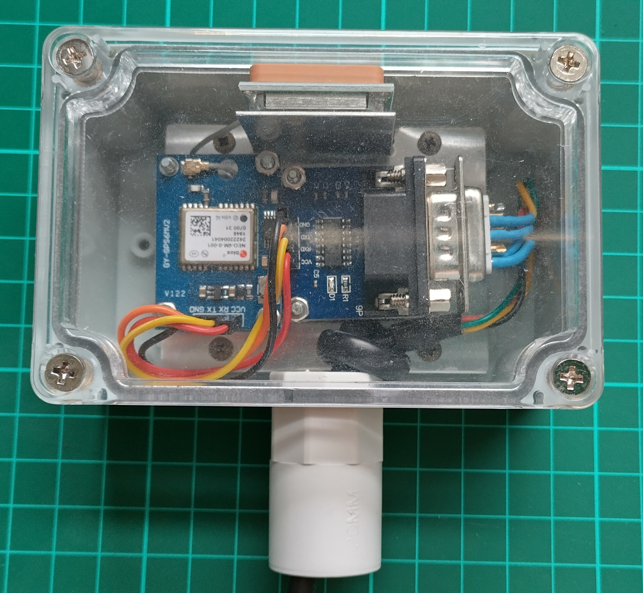
And the module installed in its box:
Click on the image to load a larger version (in a new window).
The 20 mm conduit coupling at the bottom is intended to allow the receiver to be mounted outside on the top of a piece of 20 mm conduit. A 4-core wire 4 metres long provides the interface.
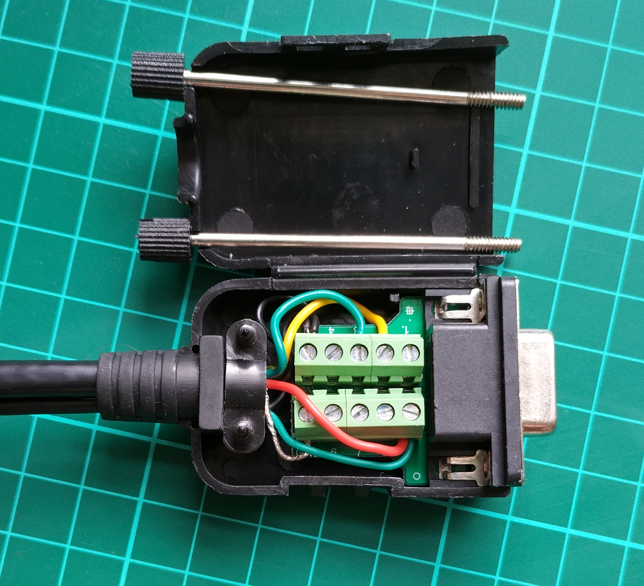
Power is fed into the 9-pin D-type on the other end of the wire:
The 9-pin D-type is the re-wireable type as this allows the wire to be inserted through a wall before terminating in the shack. Pin 9 was isolated from the D-type by cutting and removing the PCB tracking. Screw-terminal number 9 was then connected to the +VE input from the 2.5 mm power-lead. The ground connection routes to pin 5.
Click on the image to load a larger version (in a new window).
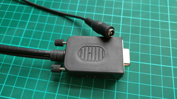
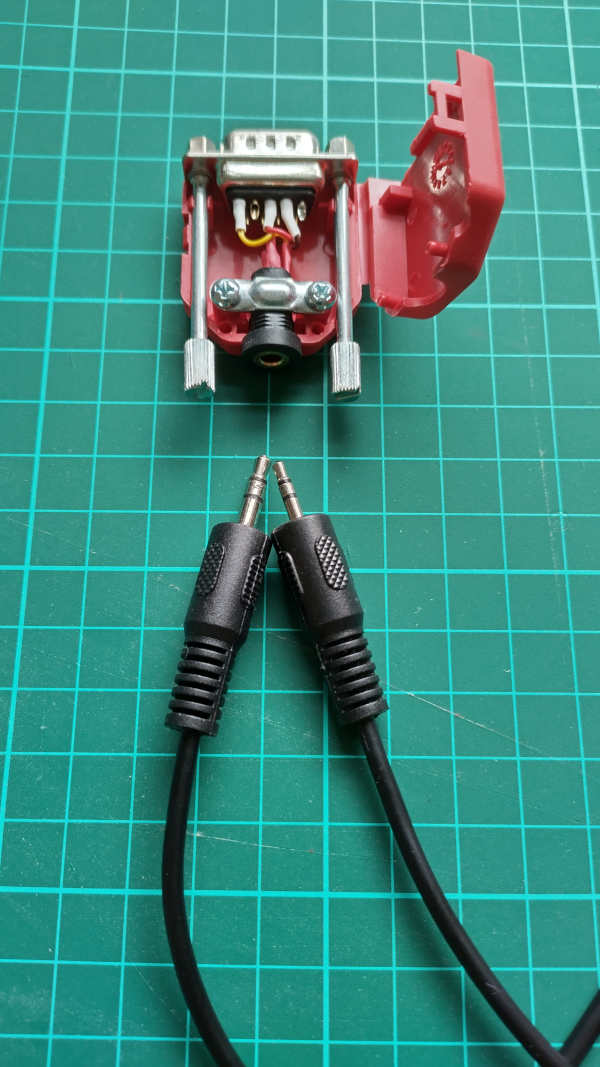
Pin 2 and 3 connect through with no twist (as that would be a null-modem link). This is the finished receiver unit with a 9-pin D-type soldered to the receiver end of the cable:
Click on the image to load a larger version (in a new window).
You can make a simple adapter to convert the 9-pin D-type to the 2.5 mm three-pin connector used on the side of the control head for the FTM-400. A 3.5mm stereo jack will fit in the rear of a D-type shell allowing the creation of a neat converter. Pin-out can be found in the FTM-400 manual. A 3.5 mm to 2.5 mm stereo lead provides the final conversion.
Programming
By default, the NEO-6 module outputs serial data at 9600 baud with all of the GPS data enabled. The FTM-400 can only take data in at 4800 baud, and it only requires two GPS data formats. It will refuse to play nice if you leave the other data sources switched on.
In order to programme the device, you will need to install uBlox uCenter software (Windows only); and your computer will need its own Serial port, or you will need a USB-to-Serial converter.
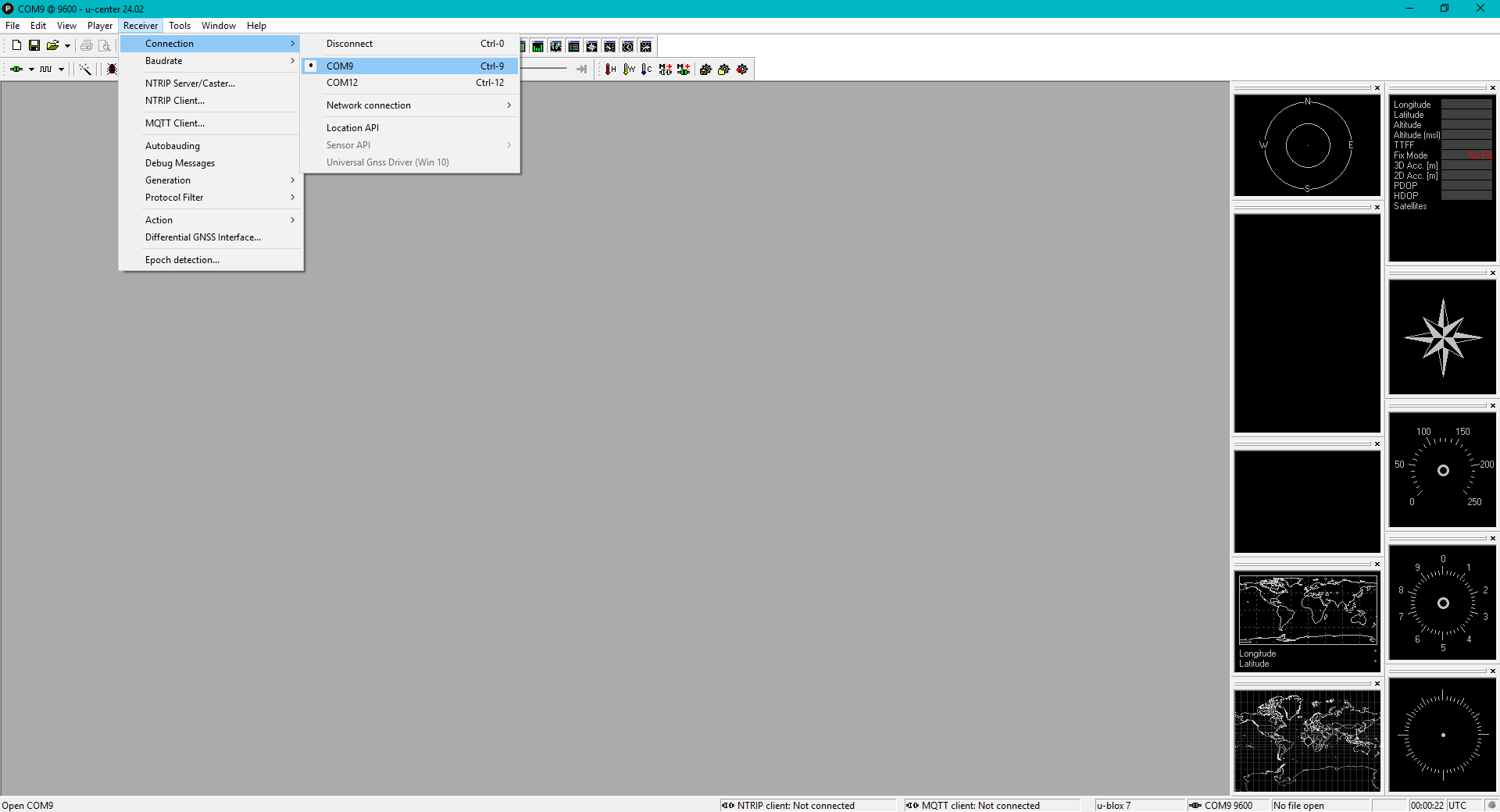
After starting the software, you will need to click on Receiver > Connection and select the COM port for the GPS module.
Click on the image to load a larger version (in a new window).
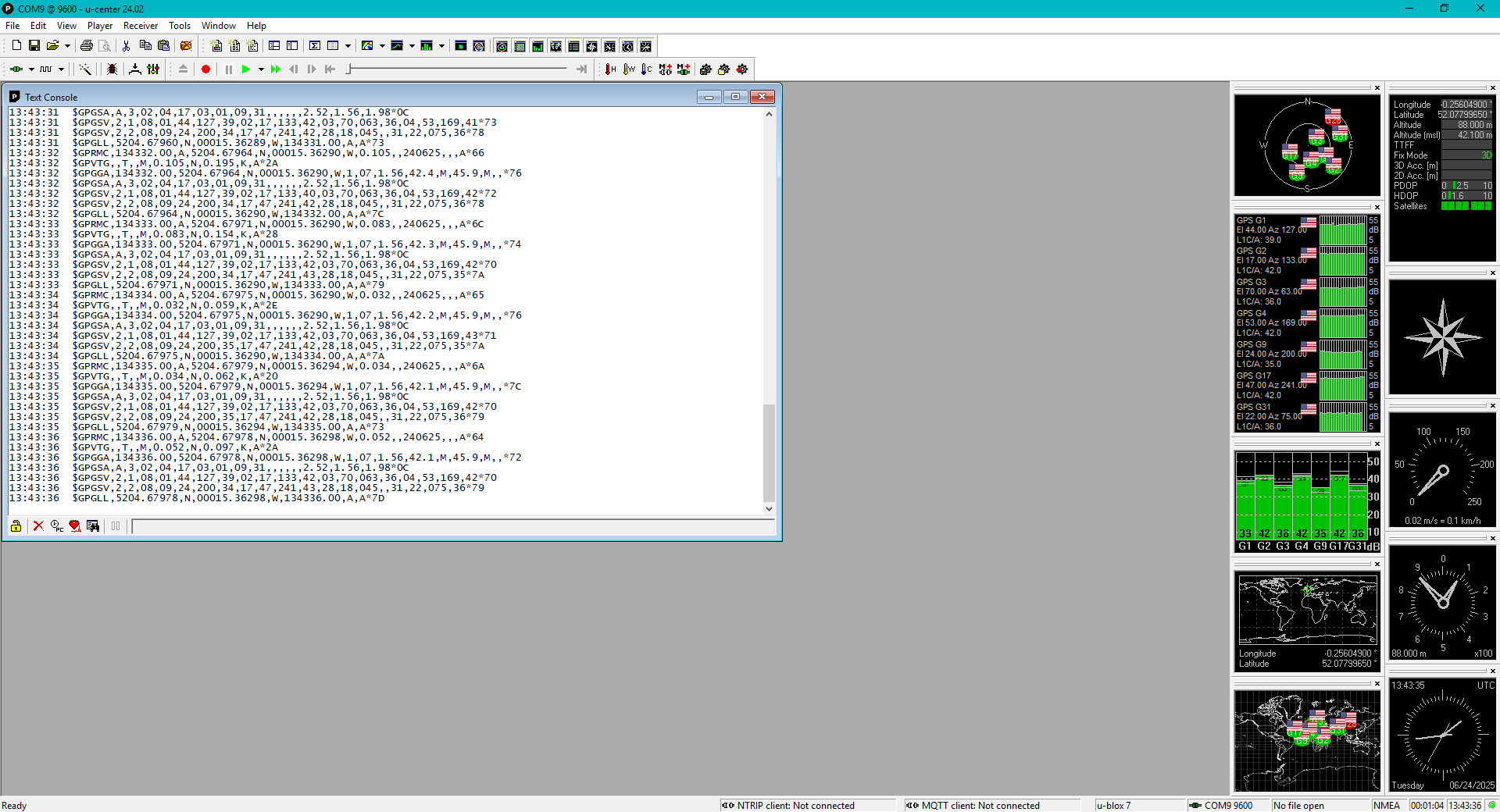
Open the Text Console (press F8) to see the output from the module. The right-hand meters should start to display GPS data. You may need to position your module outside to see the sky properly.
Click on the image to load a larger version (in a new window).
Click on View and select Configuration View (Ctrl + F9).
Click on the image to load a larger version (in a new window).
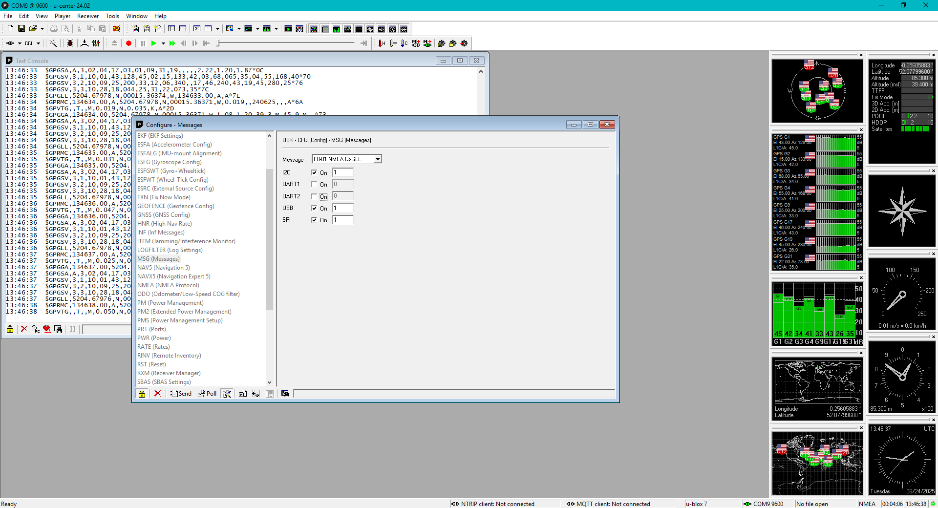
The data of interest is in the MSG (Messages) settings. Select the pull-down and for each of the messages, de-select the tick boxes against UART1 and UART2 except for GxGGA, GxGSV and GxRMC. I found it best to click the Send button for each change.
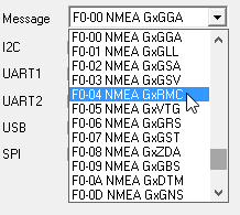
You should see the number of printed messages in the text view decrease, and the corresponding meter stop displaying the data. The two remaining should show the number of GPS satellites in view, the UTC time, and your location.
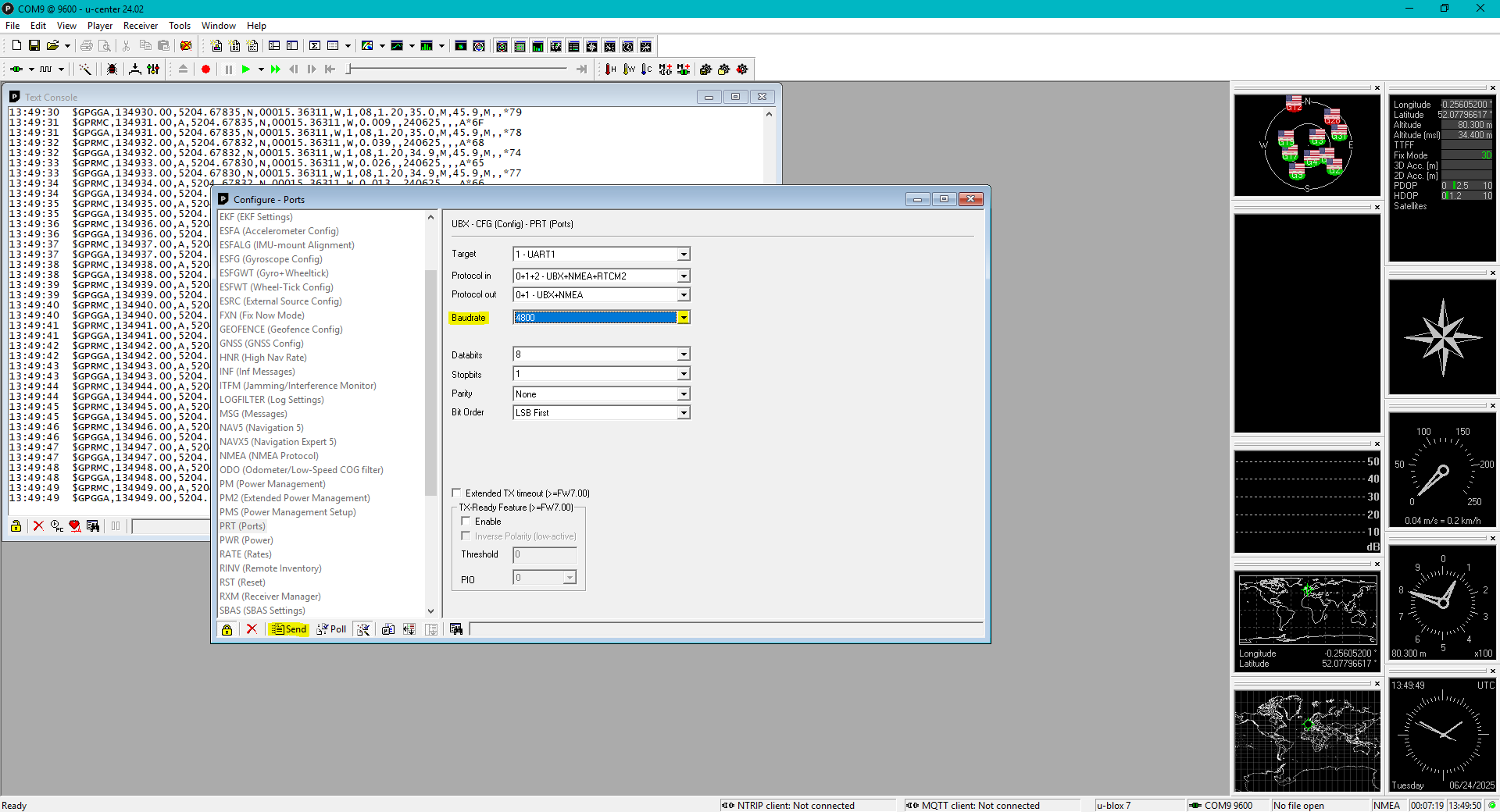
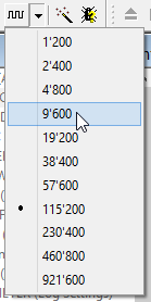
For the FTM-400, you will need to decrease the baud rate to 4800 bits-per-second. This can be found in PRT (Ports). Set the Baud-rate to 4800 and click the Send button.
Click on the image to load a larger version (in a new window).
You will need to re-configure the port to 4800 via the baud-rate menu:
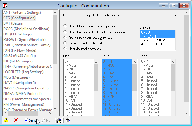
You need to write the changes to the NEO-6 module else it will default to 9600 on restart. To save them permanently use the CFG section and click Send button.
The text output should now show $GPGGA and $GPRMC output once per second:
Click on the image to load a larger version (in a new window).
FTM-400
In order to use the external GPS receiver with your FTM-400, you will need to make the following change:
Press and hold the DISP | SETUP button.
Select CONFIG
Set 17 GPS DEVICE to EXTERNAL
Press the BACK button to exit the set-up. You should see reliable GPS data and the green satellite symbol on the display. Press the DISP button to cycle through the location data (click the MY button for your location), your altitude, the time (in UTC), and the number of satellites in view.
FT-991(A)
This module project also works with the FT-991(A). If you leave the baud rate at 9600, remember to select that in menu item 029. Menu item 028 should be set to GPS1.
Page updated: 19th March 2026
Home
|
Tips
|
Awards
|
Linux
|
fldigi
|
APRS
|
QSSTV
|
WSJT-X
|
Projects
|
PSU
|
Repairs
|
Downloads
|
Links
SSTV Gallery
|
eQSL Gallery
|
MQ0PLT eQSL Gallery
|
MQ0PLT eQSL Awards